Direct Fiber Positioning System
Open Source Instruments Inc. |
Direct Fiber Positioning System
Open Source Instruments Inc. |
We submitted our Phase I SBIR grant application A Novel Dense Fiber Array for Astronomical Spectroscopy to the National Science Foundation (NSF) on December 4, 2020. We began our Phase I work in October, 2021. The NSF notified us of our award on January 1, 2022, award number 2111936. The initial grant covered twelve months of work. The NSF granted us a three-month extension in August, 2022. We completed our Phase I work in February, 2022. This document is a final report on our Phase I work. For a detailed chronicle of our Phase I work, see our DFPS Development Log.
Our Direct Fiber Positioning System (DFPS) uses the slight bending of a piezo-electric cylinder to displace an optical fiber at the end of a tube. Each fiber positioner consists of a cylindrical, piezo-electric actuator, a long tube for a mast, a detector fiber held in a ferrule, and a controller and amplifier to generate the actuator's ±250-V electrode voltages. The DFPS provides one fiber positioner per 5 mm × 5 mm square area. All electronics fit within a 25 mm2 footprint. All positioners can be adjusted independently and simultaneously. Adjustment requires no increase in power consumption. We can construct an array of one hundred thousand positioners using the same fundamental design as we would use to construct an array of eighty fibers. When combined with a spectrometer, the DFPS provides one measurement of red shift per 5 mm × 5 mm square. A fiber view camera (FVC) looks down upon the fiber tips from above. Its function is to measure the locations of the detector fibers during the spectrograph exposure. We can back-illuminate the detector fibers so they appear as point sources in the FVC, or we can back-illuminate separate guide fibers mounted adjacent to the detector fibers. Fiducial fibers distributed throughout the array, and around its perimeter, allow us to determine the location of the fibers with respect to the telescope's field of view. The FVC allows us to keep the detector fibers on their targets during arbitrarily long exposures. Our work on the DFPS since October, 2021 has been supported entirely by a Phase I Small Business Initiative Research (SBIR) grant number 2111936 awarded by the National Science Foundation.

The DFPS is the front end of a multi-object spectrograph. The back end is a system of diffraction gratings, mirrors, lenses, and image sensors that creates and records the spectra of the light from each detector fiber. The design and construction of spectrographs is challenging, but the technology and expertise to build such instruments exists. In our Phase I work, we concentrated on the design of the fiber positioners and how to mount them in a compact array. We considered how to fit the actuator control electronics in the space available beneath each positioner. We studied creep and hysteresis in the actuators. We studied gravitational bending in the masts. In Phase I, our positioners consisted only of guide fibers. We illuminated these at the far end so that they glow in the view of our FVC.
In our Phase I work, we built several prototype positioners, concluding with a 4×4 array equipped with all necessary control electronics, power supplies, and mechanical services, all fitting within the 20 mm × 20 mm area of the array. In the sections below, we present our Phase I work and compare our progress to the milestones we declared in our original application.
From January to March, 2022, we worked with our Test Stand Zero (TS0), which consisted of three fibers mounted on an optical breadboard. Each positioner consisted of a 40-mm actuator, a 300-mm stainless steel mast, a 2.5-mm diameter zirconia ferrule at the tip of the mast, and an optical fiber running down the inside of the mast to a nearby light injector. A monochrome camera looked down upon the fiber tips from above, allowing us to measure fiber position with precision 5 μm rms.

We used TS0 to study creep and hysteresis in our piezo-electric actuators. We used a spiral reset procedure to mitigate the effect of hysteresis, and we used a prediction and correction strategy to mitigate the effect of creep. Following a spiral reset, we obtain precision 10 μm rms for subsequent movements to the corners of our range of motion, regardless of where the fiber was located before the move. Once the movement is complete, the actuator creeps. By watching this creep for 200 s, we can predict where the fiber will be 1800 s later with precision 10 μm rms.
Our creep compensation procedure consists of watching the movement of the fiber for 100 s after its initial, larger movement, and fitting a straight line to its position versus logarithmic time. The creep adheres well to a logarithmic model, allowing us to predict the position of the fiber following the movement with an accuracy of ±1% of the initial movement, or roughly 10 μm rms for randomly chosen movements across the fiber's range of motion.
By combining our spiral reset and our creep compensation calculation, we can, in principle, move to any fiber to any position and hold it there for an hour with precision 10 μm rms. We call this strategy for positioning fibers, where we make use of no measurement of fiber position during the entire spectrograph exposure, dead reckoning. But we have no intention of operating the DFPS in this manner. One of the advantages of the DFPS over competing fiber positioner designs is our ability to adjust all fibers simultaneously and continuously without any significant increase in the power consumption of the control electronics. We will measure the position of all the fibers every ten minutes. Our precision improves to 5 μm rms and we have no limit on exposure time.
Milestone Three: Construct a non-miniaturized, single-fiber DFPS. Our TS0 provided three fibers.
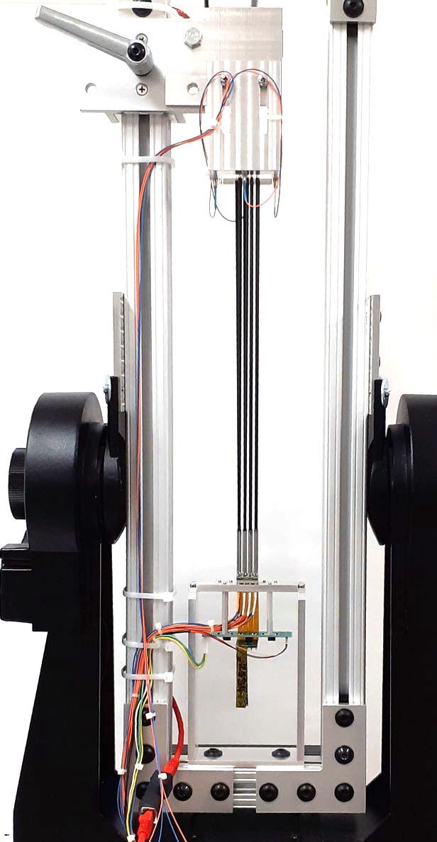
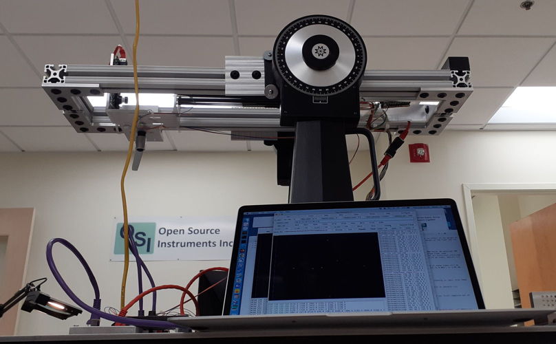
One of the weaknesses of TS0 was its vulnerability to floor vibration and the fact that we could not rotate the positioner array into the horizontal position. From April to July of 2022, we worked with our Test Stand One (TS1), which provided four fiber positioners mounted on a two-axis gimbal sitting on a vibration-absorbing optical table. The actuators were piezo-electric cylinders 40-mm long with 3.6-mm outer diameter and 2.8-mm inner diameter. They were taken from a set of sixty actuators we purchased for our Phase I work. These actuators provide four electrodes on their outer surfaces, to which the manufacturer recommends we apply up to ±250 V to cause bending. The masts were 300-mm long, 2.40 mm OD, 2.25 mm ID stainless steel tubes. At the tip and base of each positioner were 1.25-mm diameter zirconia ferrules presenting the two ends of a 125-μm diameter, 62-μm core optical fiber running down the center. To the lower end of each fiber, we connected another fiber that ran to a light injector. We made this connection with a zirconia sleeve, pushing the two fiber ends together so that they are held in contact by the static friction within the sleeve.
According to the manufacturer, the maximum bending of these actuators, provided they are constrained only at their top and bottom surfaces, is ±6.3 mrad. Our masts are 300 mm long, so the maximum movement of the fiber we can hope for is ±1.9 mm. In TS1 we constrained the bottom 3 mm of each actuator with solder joints to vertical pins, and we constrained the top 5 mm of the actuator by gluing a steel tube to its inner diameter. Both these modifications we expect to decrease the maximum movement of the fiber tip. In practice, we observed ±1.7 mm movement of the fiber tip, which is a diagonal range of 4.8 mm.

Milestone Two: Choose an actuator tube. We chose a custom-made piezo-electric tube actuator 40 mm made by Physik Instrumente. We paid $250 each for these in quantity 60. In quantity 1000, the same actuators cost $150. If we solder only to the bottom 1 mm of the actuators, and glue the mast only to the top 1 mm, we expect to see ±1.9 mm range of motion.
We used TS1 to extend our study of actuator hysteresis and creep. We showed that our spiral reset combined with our creep compensation model provided repeatability and stability of 10 μm at the fiber tip for weeks at a time. We presented our results at Snowmass in July, 2022 with our poster Direct Positioning of 50,000 Optical Fibers.
Another thing we learned from TS1 is that our steel masts deflect by ±700 μm when we rotate them into a horizontal position. At that point, we ordered custom-made carbon fiber masts, in the hope that the sag would be reduced by a factor of two in our up-coming Test Stand Two.
Milestone Four: Demonstrate better than 10-μm precision in the single-fiber DFPS, in vertical and horizontal orientations, at temperatures 25°C and −10°C. Our TS1 met this milestone at 25°C. We abandoned our plan to test the system at −10°C for two reasons. First, our choice of carbon fiber tubes greatly decreases the potential distortion of the mast due to temperature changes. Second, we no longer plan to use dead reckoning to hold the fibers on target, so predicting their movement with temperature is no longer important.
From August 2022 to February 2023, we built and studied Test Stand Two (TS2). The purpose of TS2 was to demonstrate that we can load sixteen positioners onto a 20-mm × 20-mm footprint, with all necessary control electronics and high voltage amplifiers, beneath the same 20-mm × 20-mm footprint. Each 4×4 cell of positioners must be constructed in such a way that another identical cell may be loaded on all sides, so as to continue the array with no gaps between the cells. Another purpose of TS2 was to demonstrate that our fiber controller logic and amplifiers are capable of delivering the electrical stability and precision required to place fibers with 10 μm precision, and do so while dissipating less than a few tens of milliwatts per positioner. Our focus in TS2 was upon the assembly procedure, the mechanical design of the plates and circuit boards, and the design and assembly of the electronic circuits and the miniature connectors. In TS2 we used carbon fiber tubes for our masts for the first time.
Loading the sixteen positioners onto their base board turned out to be particularly challenging. Our hope was to solder the actuator electrodes to pads on the base board with the help of solder paste and a surface mount reflow oven. But the joints we made this way were unreliable. We ended up having to hand-solder the positioners onto the base board, which was hindered by the fact that every positioner was fully-assembled with mast, and a polished 1.25-mm diameter ferrule at either end. We succeeded in loading all sixteen, but the alignment of the fiber tips was no better than ±1 mm, which meant that the fibers interfered with one another when we eventually set them to move across their full dynamic range.
At the base of each positioner is a ferrule to which we connect another optical fiber, which in turn runs to a light injector. We can flash all sixteen fiber tips independently. The TS2 masts are carbon fiber tubes. When we the masts into the horizontal position, we observe them to sag by ±350 μm with a repeatability of 10 μm rms. For pointing angles up to 45° from the zenith, we can predict the deflection of the fiber tips to better than 5 μm rms. Predicting the sag to 5 μm rms is useful as a diagnostic check of each fiber, but is not necessary to maintain the fibers on target. Our concern with the sag is that if one mast sags by 1 mm while another sags by 2 mm at the same orientation, we will be unable to compensate for sag by rotating the telescope. It appears, however, that the sag will be within ±50 μm for all masts.
Milestone One: Choose a guide tube material. We chose custom-made carbon-fiber tubes 300 mm long. We paid $75 per tube in quantity 20. In quantity 1000, the same tubes cost $35.
Packing sixteen fiber controllers beneath our array of sixteen positioners requires a connector capable of maintaining isolation between ±250 V signals, and holding each fiber controller in place with its own insertion force, all within a 25-mm2 area. Only one company makes connectors that meet these requirements: Omnetics Connector Corporation in Minnesota. In the photograph below we can see pairs of these connectors mating at the top of each fiber controller circuit.
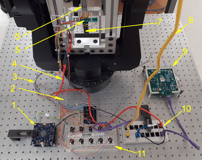

In the photograph we see a three-cell backplane board equipped with one service board. The fiber controllers are plugged into the service board. A flex cable runs from the service board up to the base board. The actuators are soldered to the base board. The flex cable can be bent at a sharp 90° angle where it emerges from both the base and service boards, thus allowing us to the 19-mm square circuit boards on a 20-mm grid.
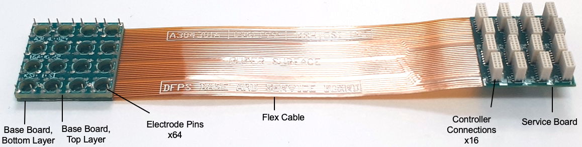
The flex cable carries all sixty four high-voltage signals required by the sixteen actuators. The fiber controllers receive high-voltage power from the service board, as well as serial logic control, both of which they share with every other fiber controller on the same backplane. Each fiber controller is addressed with its own four-digit hexadecimal identifier. The base and service board layouts were challenging. We were able to make all the required connections using 125-μm track spacing and a rigid-flex circuit, but we do not believe we could route the traces for a 5×5 cell, and certainly not a 10×10 cell. The number of traces required increases linearly with the number of positioners on the cell, but the width of the flex cable increases only as the square root of the number of positioners. We believe that 4×4 cell to be ideal for the construction of a large array.
Milestone Five: Construct a miniaturized fiber-control circuit. Sixteen of our fiber controllers fit beneath the 20-mm square footprint of sixteen positioners. Power consumption per controller is 30 mW. If we reduce the time constant of the controller's response from 100 ms to 1 s we can reduce the current consumption further to 20 mW, but the faster response made our tests much easier.
We made several mistakes during the construction of TS2. We tore off one of the connectors on the service board. After epoxying the remaining fifteen in place, we discovered that five had been deprived of their ground connection. We aligned the fiber tips poorly by hand. We broke half the electrode connections within the base board when we applied pressure to the masts. Nevertheless, TS2 demonstrates that we can pack all necessary electronics in the footprint available, and control all actuators individually.
Milestone Six: Construct a 4×4 fiber-positioning array with monitoring camera. This we did to our satisfaction. All the fibers are loaded on the array, but damage to the electrical connections prevented us from delivering drive signals to half of the fibers, and only three of sixteen receive all four of their electrode potentials. The monitoring camera provides better than 5-μm precision in measuring fiber position.
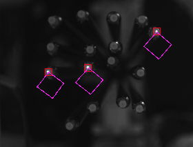
According to our fiber view camera, the range of motion of our TS2 fibers is 3.2 mm × 3.2 mm, which is significantly smaller than the theoretical maximum of ±3.8 mm. In TS2 we ended up soldering the actuators 6 mm above their bases, and we fastened the carbon fiber masts 5-10 mm from the tops. Our original assembly tooling was designed to reduced the amount by which they bend at their top end, but our original assembly plan turned out to be impractical, and we did not want to wait for another set of assembly fixtures before proceeding. The exact size of the dynamic range is not a source of great concern for us. Even ±3.2 mm covers 40% of the area occupied by the positioner. Our intended use of the DFPS is to permit each fiber to observe one object in each exposure, not to observe a particular object. According to our simulation, 40% coverage is perfectly adequate to permit a large-scale survey of the sky.

Milestone Seven: Demonstrate full range of motion, 10-μm precision, and stability of 4×4 array. The three correctly-connected positioners move in 3.2-mm squares. This 3.2-mm range is less than the maximum ±3.9 mm we can expect with ±250-V control voltages and a 40-mm actuator, but is consistent with a 40-mm actuator that is constrained for 10% of its length. Using our new controllers, we are able move and hold stationary each fiber with 5-μm precision.
On February 16th, 2023, we visited the Astronomical Instrumentation Laboratory at Texas Agricultural and Mining University (TAMU) to discuss a collaboration between OSI and TAMU on the construction of a dense fiber positioner and its installation on their 2.1-m Otto Struve telescope at the McDonald Observatory in western Texas. We formed a plan to build an eight-fiber positioner, each positioner equipped with a fiducial and measurement fiber, with measurement fibers connected to the slit of a single refurbished spectrograph, and guide fibers connected to light injectors. Both groups would be funded by a Phase II grant and both groups would collaborate on the installation and commissioning of the spectrometer. We plan to submit our Phase II SBIR application together in April 2023.
One of the things we learned while visiting TAMU is that scientific-grade CMOS image sensors are replacing the long-standing CCDs as the highest-performing image sensors for astronomical applications. The new sCMOS sensors have read noise of less than one electron, which means there is little to be gained from exposing them for long periods of time. Our original DFPS plan was to hold every fiber in position to ±10 μm by dead-reckoning after an initial two-minute monitoring period to assess starting position and creep. With sCMOS sensors, we can instead read out the spectrograph image every three minutes and spend ten seconds measuring the location of all fibers in our array simultaneously, adjusting their positions as needed, and then continue with the spectrograph exposure for another three minutes. Our DFPS no longer requires dead reckoning, but can operate as a control loop, taking advantage of the fact that our micropower, continuous-drive system for all fibers permits simultaneous adjustment of an arbitrarily large number of positioners in steps as small as one micron. Instead of needing creep and hysteresis mitigation to place the fibers correctly, we will use our understanding of creep and hysteresis to assess the health of the fibers during commissioning and maintenance periods, and to generate warnings during exposures.
In Phase I, we built a sixteen-fiber positioner on a 5-mm grid, equipped with all necessary control electronics, mounting structures, and power supplies, all packed into a 20-mm × 20-mm footprint. As a result of discussion with our collaborators at the McDonald Observatory, we simplified the operation of the DFPS by replacing dead reckoning with monitoring and adjustment during exposure. We met all our milestones, with the exception of testing the system at −10°C, which is not nearly as important to the system now that we will no longer be positioning the fiber tips by dead reckoning. Our modular DFPS design will allow us to build positioner arrays of any size, from sixteen to one hundred thousand fibers. Technical challenges that we plan to overcome in Phase II are: the development of an efficient procedure for assembling the positioner cells, increasing the range of motion of the fiber tip by increasing the length of actuator that is free to bend, and improving the durability of the service board connector array. In Phase II we will collaborate with the McDonald observatory to construct an eighty-fiber positioner, install the positioner on their 2.1-m telescope, and connect its detector fibers to a refurbished spectrometer so as to obtain spectra of celestial objects. This collaboration, if successful, will show that the DFPS is ready to be deployed for astronomical observation. It will be clear to astronomers that they can purchase from us a positioner of any size and combine it with any traditional spectrograph. If our demonstration is successful, we intend to sell 400-fiber positioners to observatories with four-meter telescopes, and to push for involvement in the construction of a Stage Five Spectrograph with 80,000 positioners.