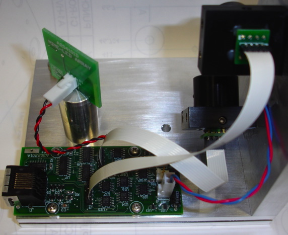
Figure: Wire Position Sensor Head Mounted on a WPS2. The cover of the WPS2 is removed.
The Wire Position Sensor Head (A3022) is a LWDAQ Device that provides two image sensors, two temperature sensors, and flashes one array of light emitting diodes. The image sensors are any of TC255, TC255P, TC236P, or TC237B. The TC255 and TC255P image sensors must be mounted on a Minimal Head (A2016), while the TC236P and TC237B image sensors must be mounted on a Minimal Head (A2070). The temperature sensors are 1000-Ω RTDs. The circuit is designed to flash an array of nine ultra-bright red light emitting diodes, whose total forward voltage drop is around 25 V.
We designed the A3022 for use with the WPS2, our second generation Wire Position Sensor. The WPS Instrument software supports simultaneous and sequential image capture from the circuit, while flashing the LED array to illuminate the field of view of the cameras. The Thermometer Instrument software supports temperature measurement with its RTDs. The LED array shown in the figure is the A2041D, with 9 red OVSA1 LEDs. The TC255 image sensors of the WPS2A are mounted on the A2016S. The TC255P image sensors of the WPS2B are mounted on the A2016P.
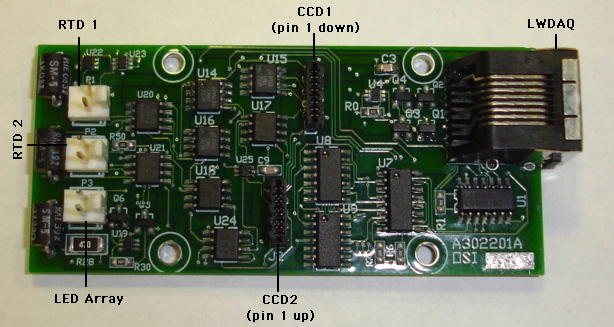
Connection to the CCDs if with 1-mm pitch eight-way flex cables, each 125 mm long. Connection to the RTDs and LED array are through twisted pair cable. The function of the A3022A is similar to that of the A2051W used in the WPS1, except the A3022A allows for simlutaneous exposure of its two image sensors, provides connection for two RTDs, and applies up to 30 V to its LED array rather than the 15 V maximum of the A3051W. The A3022W is supported by the WPS and Thermometer instruments of the LWDAQ Software, version 7.6 and higher.
The A3022 complies with the LWDAQ Specification. Its device type is 2 (TC255). The image sensors are elements 1 and 2 during read jobs, and the light source is element 1 during flash jobs. The two RTD sensors are read out with discrete LWDAQ commands, and so require no device type specification. But in the Thermometer Instrument we specify the device with its name: A3022.
| DC16 | DC15 | DC14 | DC13 | DC12 | DC11 | DC10 | DC9 | DC8 | DC7 | DC6 | DC5 | DC4 | DC3 | DC2 | DC1 |
|---|---|---|---|---|---|---|---|---|---|---|---|---|---|---|---|
| TB | X | X | T2 | T1 | X | ON1 | CCD1 | WAKE | LB | TT | TS | IAGD | SAGD | SRGD | DCEN |
The signals acronyms are DCEN for direct clock enable, SRGD for serial register gate digital, SAGD for storage area gate digital, IAGD for image area gate digital, and LB for loop back. The CCD1 signal, when asserted, selects the image sensor connected to J3. The ON1 bit turns on the LED array.
The TB, TT, T2, T1, and TS bits control the readout of the two RTD sensors. We select the temperature sensor readout instead of the image sensor readout by asserting TS (Temperature Select). We select the top reference resistor, bottom reference resistor, sensor one, and sensor two with bits TT, TB, T1, and T2 respectively.
The performance of the radiation-resistant diode-chain voltage regulator, formed by U5 and U6 here limits the recommended operating temperature of the A3022 to 0°C to 75°C, as we describe in Diode Regulator.
The A3022 is the first LWDAQ Device that allows us to expose two image sensors at the same time, and read them out sequentially. All other dual-image devices, such as the WPS Head (A2051W), supported only separate exposures. The A3022 achieves simultaneous exposure of its two TC255Ps by allowing us to separate the SAG (storage area gate) input of the second sensor, which we call CCD2, and connect it to −10 V. Thus the image in the storage area of CCD2 remains in the storage area while the image in the storage area of CCD1 is read out by the LWDAQ driver. The SAG input of CCD2 is connected to −10 V when we set the command word bit CCD1. The connection is performed by U24 as shown in S3022_3.gif. The CCD1 bit also selects the output of CCD1 for return on R+/R−. Component U17 performs the selection. When we first assert CCD1, the R+/R− output will jump because we must charge the coupling capacitor C10 before we establish the high-pass filter connection between the CCD1 output and R+/R−. This charging takes place with a time constant of about 10 μs, so we must allow at least 30 μs for it to settle. In the WPS Instrument code, we execute a wake job before we execute a read job, and this inserts a delay equal to the time it takes the LWDAQ driver to process on TCPIP message. On our fastest driver, the A2071E, this execution time is at least 40 μs.
[14-MAR-19] We have six A3022B first article from assembly house. All six are 100% functional. We take the first A3022B and measure top and bottom reference temperatures, the temperature of an RTD glued to a WPS end wall, and a 0.01% wire-wound 1080-Ω resistor. We use s/div 0.0017 to eliminate mains hum. Standard deviation of all four temperature measurements is 2 mK. We try an A3022A and obtain standard deviation 1 mK. The A3022B bottom reference temperature is 15.387°C, compared to ideal 15.380°C (A3022A is 15.48°C). The A3022B top reference is 25.689°C compared to ideal 25.690°C (A3022A is 25.690°C). The A3022B for 1080.0 Ω is 20.528°C compared to ideal 20.535°C (A3022A is 20.542°C). We find that the crimp contacts on our 1080-Ω resistor wires are intermittent. We connect all six A3022B to the wall-mounted RTD in succession and obtain a standard deviation of 0.008°C.