Making ISL Tapers
© 2014 Michael Collins,
Open Source Instruments Inc.
Contents
Introduction
Hardware
Software
Procedure
Introduction
This page describes how to operate the Optical Fiber Tapering Machine to manufacture tapers for the Implantable Sensor with Lamp. The machine accepts an optical fiber with 450μm diameter that is polished at one end. It tapers this fiber to a point resulting in a fiber that is 8mm long. Starting at the polished end, the first 6mm of the fiber have a uniform diameter of 450μm. The final 2mm of the fiber tapers from this uniform diameter to a point.
Hardware
For a description of the Optical Fiber Tapering Machine visit its page. There are only two hardware modifications implemented in the production of ISL tapers.
The first modification is the switch from a gas flame heat source to an electric heating element. The electric heating element is made from 0.40mm diameter nichrome wire (specified at 2.572 ohms/ft). To make the heating element, the wire is wrapped tightly into four turns around a 2.5mm hex key. Each turn is separated very slightly from one another by a fingernail or thin ruler's edge while still wrapped around the hex key. The turns should be as close to one another as possible without touching. The hex key is then removed, leaving a self-supporting nichrome coil. Its two ends are clipped to a current source with alligator clips.

Figure: The heating element has an internal diameter of 2.5mm and is made of four turns of 0.40mm diameter nichrome wire. Its leads are held by alligator clips.
The second modification is the inclusion of a stopper wire. This is a length of wire glued into one of the grooves which the fiber sits in. It provides a backstop against which the fiber is placed so that the fiber can be placed in the same position every time and make consistent tapers.
Software
The ISL taper tool (isl_taper.tcl) is used with the LWDAQ to control the tapering machine. Running this code with its default values will create the previously described 8mm tapers suitable for the ISL. In the event that the stretching machine is modified (a heating coil is replaced, for example), the machine may begin making tapers shorter or longer than the desired 8mm. In that case, the machine can be calibrated using the variable "offset 1". This variable describes the amount that fiber is translated (in millimeters) before the stretching process begins. Modifying this value will result in shorter or longer tapers as desired.
Procedure
- Polish one end of an optical fiber. At the polished end, its diameter should be between 440μm and 460μm. The fiber must be at least 7cm long to be accepted by the tapering machine. A 12-14cm fiber is recommended since it is easier to handle.
- Load the isl_taper.tcl tool. Press "Home Position". Wait for both motors to move and then come to a stop. When both motors are stopped, the translating stages are at the home position.
- Place the fiber into the groove closest to the edge of the holding plate. It should pass through the heating element and its polished end should rest against the stopper wire. It can be held against the holding plate which does not include the stopper wire with one thumb. Rotate the fiber so that its natural bend makes it bend directly into the other holding plate (that which includes the stopper wire). When the correct position is achieved, clamp the fiber to the holding plate next to the stopper wire with the magnet. Apply slight tension to the fiber with one finger in order to straighten it while clamping it with another magnetic to the other holding plate.
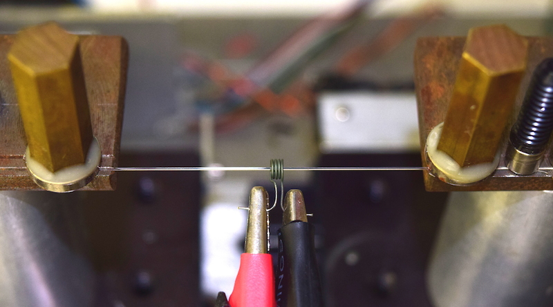
Figure: The fiber properly held in place by magnetic clamps passing through the heating element. It is pressed into a groove in each of the holding plates. On the right side, its polished end is pressed against the stopper wire (beneath black magnet clamp).
- Press "Load Stretch Settings" and wait for the program to confirm with the text "Program Loaded". This step only needs to be performed once per stretching session. Once loaded, the program remains in the motor index drives until their power supply is interrupted.
- Turn on the power supply attached to the heating element. Adjust the current to be between 4.15A and 4.20A if necessary. This adjustment is most easily made by leaving the current adjustments at their maximum positions and adjusting the fine voltage dial. The coarse voltage dial should only be used if necessary.
- Press "Begin Stretching" and wait for the motors to move and then come to a stop.
- Turn off the power supply to the heating element and allow it to cool. Carefully remove the completed taper from the holding plate. If the magnetic clamp is liften cleanly away from the holding plate instead of dragged, the taper will remain in the groove and can then be removed with fingers.
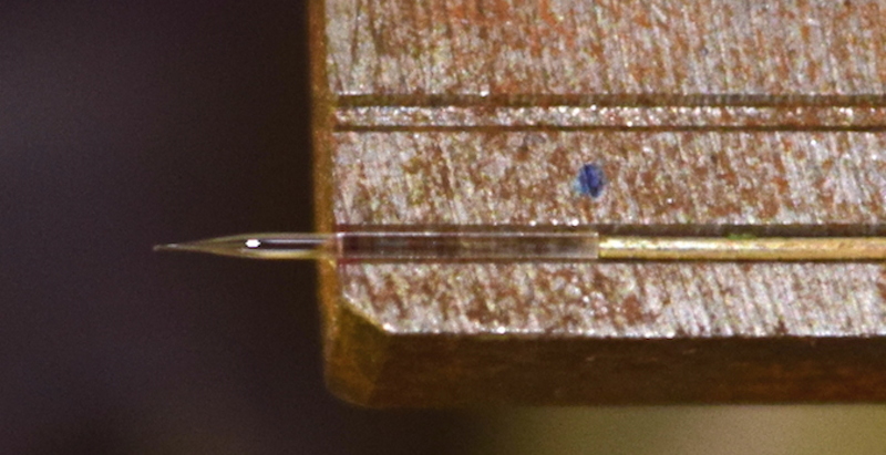
Figure: The taper is shown after the stretching procedure. The magnetic clamp has been removed and the fiber is ready to be removed with fingers. The stopper wire is visible to the right of the fiber. The burr at the tip (barely visible) can be removed with polishing film.
- Inspect the taper for a fine burr at its tip. If one is present, remove it with 15μm polishing film held in the air to prevent damage to the fiber.