 Animal Cage Camera (A3034) Manual
© 2018-2026 Kevan Hashemi,
Open Source Instruments Inc.© 2018 Michael Collins, Open Source Instruments Inc.
[22-JAN-26] The Animal Cage Camera (ACC version A3034) operates with the Videoarchiver Tool to provide high-definition, compressed video that is synchronous with biometric signals recorded by our subcutaneous transmitters (SCTs). The ACC is a black-anodized aluminum cuboid that sits securely on a flat surface for horizontal viewing, mounts in a mobile phone stand for elevated viewing, and fits behind the cages of a an individually ventilated cage (IVC) rack where we can zip-tie it to the ventilation pipes. The camera itself is roughly 88 mm × 98 mm × 55 mm, not counting the lens and cable.

The ACC provides independent, variable-intensity, white and infrared light-emitting diodes (LEDs) to illuminate their own field of view. With the help of a day-night program running with the Videoarchiver, we can alternate between white and infrared light do simulate night and day. Its lens has no infrared blocking filter. The lens provides gray-scale images in infrared light, and balanced, crisp, full-color images in the light of its white LEDs. With the help of the Videoarchiver's scheduling component, we can alternate white and infrared illumination during day and night hours, and so obtain full-color images during the day, and gray-scale images at night.
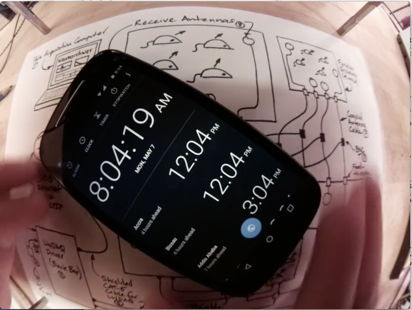
The ACC offers three significant advantages over commercially-available webcams. Its video recordings are synchronous to ±100 ms with respect to a central data acquisition computer's clock. We can place the camera right up against an animal cage wall and view the entire cage without seeing its own infrared or white LEDs reflected in the wall. We can use the ACC recordings directly with the Neuroplayer to navigate through telemetry recordings.
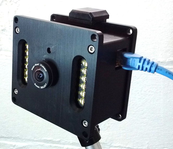
Power and communication are provided to the ACC by a single Power-over-Ethernet (PoE) cable. A single PoE switch with twelve or more ports allows us to connect ten ACCs, a LWDAQ Driver, and a data acquisition computer to the same local network. With such a network, we can record biometric signals from dozens of animals, along with synchronous video of those same animals from ten different points of view. The A3034C's wide-angle DSL227 lens and IMX219 full-color image sensor together provide a 148-degree diagonal field of view. When delivered by OSI, the center of the A3034C's depth of field is at range 40 cm, which provides sharp images of objects from ranges 20 cm to infinity. We say the focal range of the camera is 40 cm, and the depth of field is 20 cm to infinity. If we want to view objects 10 cm away, we adjust the lens-fastening screws so they allow the lens to rotate smoothly but with resistance, so the lens will remain where it is when we let go of it. WE rotate the lens counter-clockwise to reduce the focal range. We do not tighten the screws after we adjust the focal range, because tightening the screws moves the lens and changes the focal range. The A3034C offers two video output formats. The A3034B-HR format is 820 pixels wide and 616 pixels high (820 × 616) at twenty frames per second (20 fps) with standard-quality output. The A3034B-LR format is 410 × 308 at 30 fps with high-quality output. The video files produced by both formats take up roughly 5 GByte/day when viewing animals in a cage with infra-red illumination at night. The low-resolution format provides sharper images of fast-moving animals, while the high-resolution format provides sharper images of small, slow-moving animals.

The ACC is intended for operation in clusters of up to ten cameras, all controlled by one Videoarchiver Tool. The Videoarchiver provides live display of camera video on the computer screen for use when you set up your camera. The delay between movement in the camera field of view and its appearance in the live display should be less than fifty milliseconds. To record video to disk, we stop the live display, and instead initiate segmentation and compression of video on the camera itself, which the Videoarchiver downloads and concatenates into time-stamped video files that are synchronous with the local data acquisition computer clock. While recording to disk, we can view the compressed video as it arrives at the data acquisition computer, but this view will be delayed by several seconds. This delay does not represent a lack of synchronization with the local clock.
The video produced by the A3034 is compressed with the H264 algorithm using crf=23 (constant rate factor set to twenty-three), which provides well-defined images of moving animals. A ten-minute, 820 × 616, 20 fps video of moving animals will occupy roughly 30 MBytes on disk. The compressed video contains key frames at the start of every whole second marked by the data acquisition computer's clock. These key frames allow the Neuroplayer to jump quickly and accurately to any whole-second boundary within the video recording, and at the same time display the simultaneous biometric signals with synchronization accuracy ±50 ms.
The ACC is designed to be quiet and reliable. Its power converters are long-live, encapsulated devices run at frequencies well above the ultra-sonic frequencies mice can hear. The ACC contains no fan. It dissipates the heat generated by video compression by means of conduction, radiation, and un-forced convection alone. During video recording, its case will be 15°C warmer than ambient. The PoE switch that supplies power and communication for the cameras should be quiet also. We recommend a switch such as the GS116PP, which has no fan and provides more than 12 W electrical power for each of ten cameras.
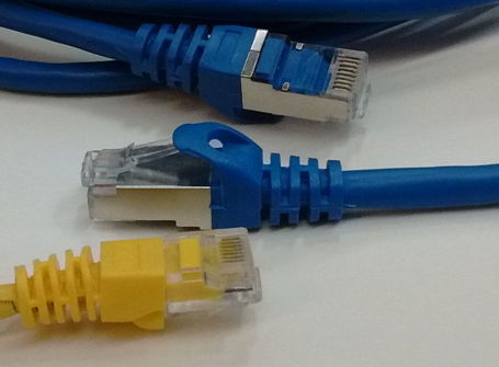
Each ACC requires only one cable for power and communication, but we must use the right kind of cables. For gigabit PoE connections, we must use Cat-5E or higher network cables. The A3034B (cameras S0205-S0217) requires that we use unshielded cables from the switch to the Faraday enclosure because of a weakness in its design. The A3034C and later versions work fine with either shielded or unshielded cables from the switch to the Faraday enclosure. Our subcutaneous transmitters systems almost always operate within some kind of Faraday enclosure, such as the FE3AS). These enclosures are designed to be electrically quiet, both at the low frequencies of biometric signals, and the much higher frequencies of radio-frequency interference. When we install a camera inside such an enclosure, we rely upon the aluminum case of the camera to keep its own electrical noise contained, but we must in addition use a shielded network cable between the camera and the Faraday enclosure wall. Thus, we always use a short, shielded network cable to connect the feedthrough to the camera inside the enclosure. If we do not use a shielded cable inside the enclosure, we introduce mains hum and radio-frequency interference into the enclosure volume.
[18-MAR-25] We can equip the A3034 with a variety of lenses, each of which gives the camera a different field of view and color balance. As time goes by, we adapt the A3034 to accommodate changes in the third-party software and hardware that we use to construct the cameras.
| Version | Features | Image Sensor | Lens | FOV | Video | Markings |
|---|---|---|---|---|---|---|
| A3034B1-A | Raspberry Pi 3B+, raspivid interface. Requires unshielded cable to Faraday enclosure |
IMX219 | DSL227 | 148° | 820 × 616, 20 fps, H264, crf=23 |
None |
| A3034C1-A | Raspberry Pi 3B+, raspivid interface. | IMX219 | DSL227 | 148° | 820 × 616, 20 fps, H264, crf=23 |
None |
| A3034C2-A | Raspberry Pi 3B+, libcamera interface. | IMX219 | DSL227 | 148° | 820 × 616, 20 fps, H264, crf=27 |
Orange Dot |
| A3034C2-B | Raspberry Pi 3B+, libcamera interface. | IMX219 | DSL215 | 180° | 820 × 616, 20 fps, H264, crf=27 |
Orange Dot |
The original A3034 cameras used the raspivid library interface on the Raspberry Pi 3B+. This interface was later retired and rendered obsolete by Raspberry Pi. We could no longer buy camera modules that supported the raspivid library. We were forced to move to the libcamera library and purchase the newer camera modules. But it turned out that the color balance we obtain with the new library is significantly better than with the old.
Warning: Do not over-tighten lens screws. Over-tightening spoils the camera focus.
Warning: Do not plug the camera into a LWDAQ Driver. Doing so will damage the camera.
[07-DEC-23] In order to communicate with your ACC when you first receive it, you must configure your computer's wired Ethernet interface to communicate on subnet 10.0.0.x. You assign your computer an IP address like 10.0.0.2, and you give it "subnet mask" 255.255.255.0. On MacOS, create a new location with the Locations Manager, which is accessible through the Networks icon in System Settings. Select your wired Ethernet connection and configure it using the graphical user interface of the Locations Manager. We have specific instructions for Windows 7 and Windows 10. On Linux, you edit file /etc/dhcpcd.conf to configure your wired ethernet interface, which may be called eth0, or may be called something long and cryptic if you have "predictable interface names" on your version of Linux.
The diagram below shows how four ACCs, a data acquisition computer, and a LWDAQ Driver (A2071E) connect to the same local network provided by a single PoE switch. Two cameras are set up outside a Faraday enclosure, and two more are set up inside the the Faraday enclosure. An Octal Data Receiver A3027E is connected to the LWDAQ Driver and to two Loop Antennas (A3015C) within the same Faraday enclosure. These antennas receive signals from subcutaneous transmitters (SCTs) implanted in the same animals the cameras are arranged to view.
We must use shielded network cables inside the enclosure. From the enclosure wall to the PoE switch, we can use shielded or unshielded cables if our cameras are version A3034C or later, but for the A3034B (cameras S0205-S0217) we must use unshielded cables from the enclosure to the switch.
The ACC and SCT recording system requires three connections to AC wall power. The data acquisition computer, PoE switch, and LWDAQ Driver each connect to AC power with their own power adaptors. Power for the cameras is delivered by the PoE switch through network cables. When we first connect power, the camera will boot up. Its white lights turn on to full power, then dim to half-power. After about thirty seconds, the white lights flash three times, indicating that the camera is ready to run. On the front face of the A3034 there is a hole, and behind this hole is its configuration switch. Press this switch with a pointed object while the white lights are flashing three times, and you will reset the camera's static IP address to the value 10.0.0.34. The white lights will flash rapidly five more times to confirm that the new IP address has been implemented.
We do not ship the ACC with address 10.0.0.34. Instead, we ship each with an IP address 10.0.0.X, where X we obtain from the last three digits of the camera's serial number. The serial number label is just above the camera's RJ-45 socket. Camera S0205 ships with IP address 10.0.0.205, and camera V0054 ships with IP address 10.0.0.54. The ACC always operates with a fixed, or static, IP address, and will never permit its IP address to be assigned by the dynamic host communication protocol (DHCP) that operates on all institutional networks. The ACC is designed to operate on an isolated, gigabit, PoE network, in which there is no possibility of any external client connecting to the camera, hijacking its video, or infecting it with a computer virus. But the Videoarchiver allows us to change an ACC's static IP address to any other value we like, at the press of a button. We must, however, know the existing IP address of the camera in order to communicate with it, so if we have lost all record of an ACC's IP address, we must resort to resetting the camera's IP address to 10.0.0.34 with the configuration switch.
We could, for example, configure our camera to use a static IP address on our own local laboratory network, perhaps its subnet is 129.33.33, and we assign our camera address 129.33.33.89. If we want to make it impossible for the camera to communicate with devices outside the 129.33.33 subnet, we leave the camera's "router address" set to "0.0.0.0". But if we want the camera to be available over the wider internet, we can set the router to "129.33.33.1", or whatever the address of our subnet's router might be.
To set up your cameras, open the Videoarchiver in the Tool Menu of our LWDAQ program. Before you use the Videoarchiver for the first time, you must download and install the Videoarchiver Libraries. Having done this, enter the IP address of one of your cameras in one of the IP entry boxes, and try turning on and off the white LEDs. If you see them turning on and off, the camera is connected and ready. You can also use the Query button (if available in your Videoarchiver) to download log files from the camera, which also serves to show that the camera is ready to stream or compress video. The Live button gives you a live picture, and you can use this to check the focus of the camera, and choose the illumination intensities necessary to provide the best color balance and contrast during day and night recording. The exposure compensation setting allows you to get a better view of dim objects or bright objects. The rotation settings allow you to pre-rotate the incoming video so it will be recorded the right way up. The version setting allows you to pick the resolution and frame rate of the video you record.
[07-MAY-19] Our preferred supplier of lenses is Sunex. The table below summarises the properties of a few lenses when used with the A3034's IMX219 image sensor. This sensor is 3.7 mm wide and 2.8 mm high. The horizontal field of view of a lens when combined with the IMC219 image sensor is the angular field of view of the camera along the 3.7-mm width of the sensor. The diagonal field of view is the field of view along the 4.8-mm diagonal of the sensor. The field of view provided by a lens is always a circle. If the circle just fills the width of the sensor, our image will have dark corners, and the horizontal and diagonal fields of view will be the same. If the circle just fills the entire sensor, the diagonal field of view will be greater than the horizontal. We prefer to equip the A3034 with a lens that fills the entire sensor with its image.
| Lens | Effective Focal Length (mm) |
Horizontal Field of View (deg) |
Diagonal Field of View (deg) |
Comments |
|---|---|---|---|---|
| DSL212 | 2.0 | 102 | 140 | Full sensor image, Cost $50 |
| DSL215 | 1.6 | 135 | 180 | Full sensor image, sharp focus, cost $100 |
| DSL216 | 1.3 | 187 | 187 | Circular image, sharp focus, cost $100 |
| DSL219 | 2.0 | 116 | 160 | Full sensor image, sharp focus, cost $100 |
| DSL224 | 2.2 | 98 | 134 | Full sensor image, cost $50 |
| DSL227 | 2.0 | 108 | 148 | Full sensor image, sharp focus, cost $100 |
| DSL853 | 8.0 | 24 | 32 | Full sensor image, sharp focus, $50 |
The lenses that give sharp focus across the entire field of view cost twice as much as those that provide only one of these two qualities. The DSL212, for example, provides a wide field of view, but at $50, it does not provide resolution to match our image sensor.


The DSL219, on the other hand, provides sharp images and great depth of field over its 116° field of view, but at a cost of $100. We include a lens like the DSL219 with each A3034 camera we ship. If you have space to look down upon a rectangular animal cage from a height of 30 cm, this is the lens we recommend.


The DSL227 provides a wide field of view, splendid, sharp focus, and great depth of field. It is also a $100 lens. If you want to place your lens close to a rectangular animal cage, this is the lens we recommend.


We suggest you consider the depth of field and angular field of view your application demands, and then we will choose with you a lens that provides the best use of the image sensor to provide bright, sharp images of your animals.
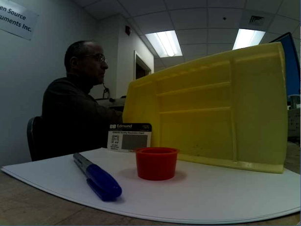
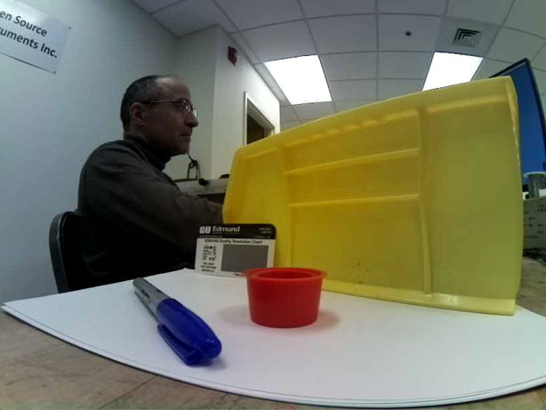
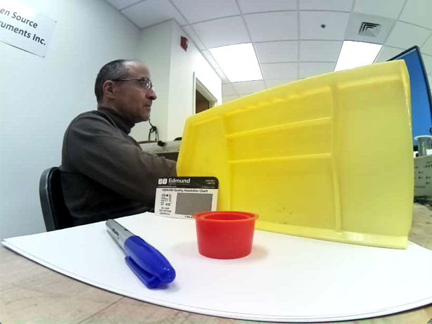
The above image shows near objects out of focus and distant objects in focus. The focal range of the camera is infinity, meaning we have made the focus sharp for distant objects. By default, we focus the A3034 at range 40 cm in the factory before we ship. You can adjust the focus by turning the lens and watching a live image.
[09-JUN-22] The A3034 camera adjusts its exposure time automatically to suit the illumination in the image. But it can favor the dimmer parts of the image or the brighter parts of the image, and we control which parts it favors by setting its exposure compensation.


The Videoarchiver allows us to set the exposure compensation value to any integer between 0.0 and 1.0 with a menu button. Once recording begins, we cannot adjust the compensation without stopping and starting again.
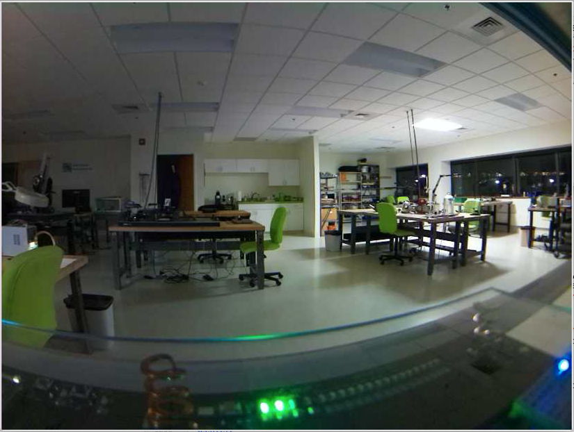
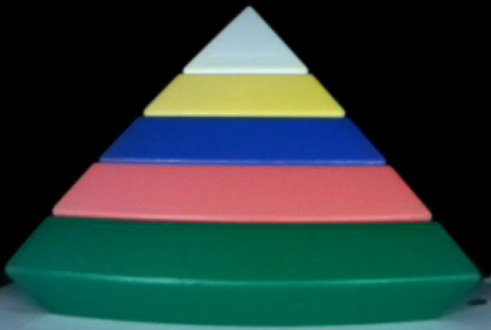
In the photos above, colors are rendered better because the lighting is better, but also because the A3034C2 provides better color balance, exposure compensation, and color saturation than the A3034C1 camera.
[21-JAN-23] In the Videoarchiver, we can adjust the brightness of colors with the color saturation value. The Videoarchiver allows us to set the color saturation to any integer between 0.0 and +1.0 with a menu button. Once recording begins, we cannot adjust the saturation without stopping and starting again. The photographs below shows how the saturation value brightens the colors in A3034C1 video.


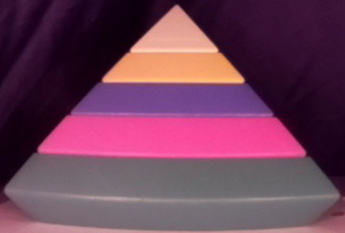
The A3034C2 camera uses the libcamera video routines instead of the older raspivid routines. The result is superior handling of color brightness, as we can see in the example image below, taken from an A3034C2.


We recommend a saturation value of 0.5 for looking at animals in dimly-lit cages, but we leave it to the experimenter to find the value that gives the best color contrast for animal viewing.
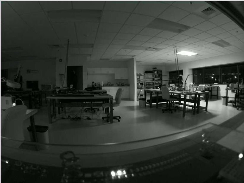
[17-JUN-25] A standard ACC is equipped with a lens that focus images of both visible and infrared light. The camera obtains gray-scale images by the light of its own infrared lights at night, and full-color images by its own white lights during the day. Sunlight contains infrared light as well as white light, so the images we obtain with the ACC in sunlight appear purple, as we can see in the image below, where the view out the windows is purple.

In white LED light, such as the white light provided by the ACC's white lamps, the IMX219 image sensor provides bright, accurate color images like the one shown on the left below.
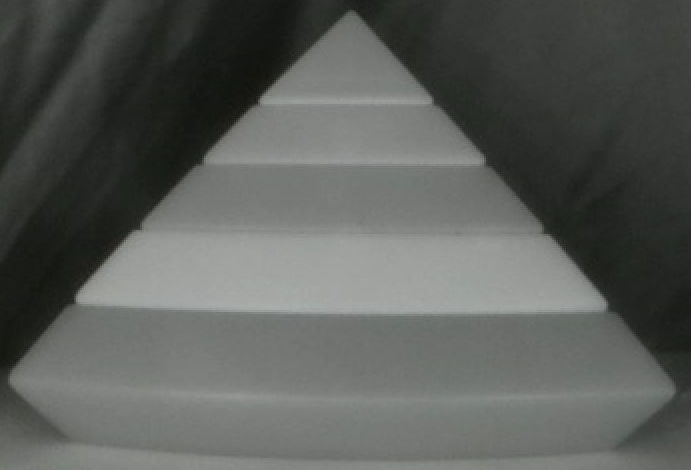
In infrared light, the camera provides a monochrome image. Its red, green, and blue pixels are all equally sensitive to infrared light, so no colors emerge in infrared illumination. When we mix the two, we get shades of red and blue, but green objects appear gray. Sunlight and incandescent lights provide a mixture of visible and infrared light. The ACC with its standard lenses provides poor color balance when viewing objects in natural light or in rooms lit with light bulbs. We can, however, equip the ACC with an infra-red blocking lens if your application uses natural light exclusively.
We do not have the relative response of the IMX219C image sensor, but we expect it to be much the same as that of the IMX334C, shown above. The A3034A's infrared emitter is the APT2012F3C, with peak emission wavelength 940 nm. Our white LEDs are the L130-2780, which appears to the human eye to be the same color as an object at 2700-Kelvin. The actual emission spectrum of the LED is not a black-body emission spectrum, as shown below.
The white LED is actually a blue LED covered with yellow phosphor. The result is a combination of blue and yellow light that appears to our eyes to be the white. The color of objects in this light, may not be the same as the color they would appear in incandescent or fluorescent light. We adjust the color balance of our cameras to provide the best colors in the light of the camera's own white LEDs. If you see variation in color balance across your camare field of view, try updating to the latest Videoarchiver and then updating your camera color balance with the update button. The update will install the latest color balance tables.
[09-JUN-25] For design files and development logbook, see the A3034 design and development page at D3034.