Canopy Feedthrough (A3039)

© 2020-2021 Jordan D. Kaufman, Open Source Instruments Inc.
© 2021-2023 Kevan Hashemi, Open Source Instruments Inc.
© 2022 Nathan Sayer, Open Source Instruments Inc.

Contents

Description
Versions
Design
Set-Up
Modifications
Development

Description

[17-MAR-23] The Canopy Feedthrough (A3039) is any one of a family of connector assemblies that carry signals into our Faraday Canopies without compromising the canopy's electrical isolation. Within the canopy, Subcutaneous Transmitters (SCTs) and other telemetry devices can operate without disruption from ambient radio-frequency interference.


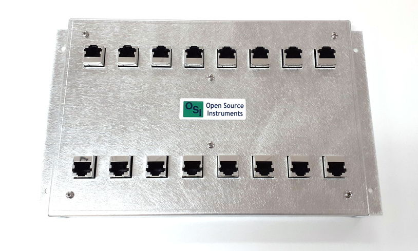
Figure: Coaxial Feedthrough (A3039E). Designed for use with a Faraday canopy such as the FE5A.

If we simply run cables under the canopy without a feedthrough, the cables will pick up ambient interference where they are outside the enclosure, and carry this interference into the enclosure, thus compromising the canopy's electrical isolation, and in extreme cases rendering the canopy ineffective.


Figure: Ethernet Feedthrough (A3039F). Designed for use with a Faraday canopy such as the FE5A.

We fasten the feedthrough to the aluminum floor that comes with the Faraday canopy and drape the bottom of the canopy itself between the two rows of connectors on the feedthrough assembly. The canopy is made of steel mesh, which makes electrical contact with the top side of the feedthrough. Cables outside the enclosure connect to the cables on the outer side of the feedthrough, and their signals continue on into the enclosure from the connectors on the inside of the enclosure.

Versions

The table below lists the existing versions of the The Canopy Feedthrough (A3039).

Version Name Connector Positions Comments
A3039A 8-to-8 Coaxial Feedthrough Coaxial 8-8 Right-angle BNC sockets, no enclosure, obsolete.
A3039B 8-to-8 Ethernet Feedthrough Ethernet 8-8 Right-angle RJ-45 sockets, no enclosure, obsolete.
A3039C 8-to-4 Coaxial Feedthrough Coaxial 8-4 Vertical BNC sockets, combines four pairs, no enclosure.
A3039D 8-to-8 Ethernet Feedthrough Ethernet 8-8 Vertical PoE RJ-45 sockets, no enclosure, obsolete.
A3039E Coaxial Feedthrough Coaxial 8-8 Vertical BNC sockets, enclosure.
A3039F Ethernet Feedthrough Ethernet 8-8 Vertical PoE RJ-45 sockets, enclosure.
Table: Versions of the Canopy Feedthrough (A3039).

We started by naming each feedthrough after the number of inputs and outputs, but in the end, we settled upon eight-way straight-through assemblies in enclosures, and we drop the "8-to-8" for the sake of brevity.

Design

S3039A_1: A3039A Schematic.
A303901A.zip: Top layer PCB for A3039A.
A303902A.zip: Bottom layer PCB for A3039A.
S3039B_1: A3039B Schematic.
A303901B.zip: Top layer PCB for A3039B.
A303902B.zip: Bottom layer PCB for A3039B.
S3039C_1: A3039C Schematic.
A303901C.zip: To layer PCB for A3039C.
A303902C.zip: Bottom layer PCB for A3039C.
S3039D_1: A3039D Schematic.
A303901D.zip: Top layer PCB for A3039D.
A303902D.zip: Bottom layer PCB for A3039D.
S3039E_1: A3039E Schematic.
A3039E_Assy: A3039E Assembly Drawing.
A303901E.zip: PCB for A3039E.
A3039F_Assy: A3039F Assembly Drawing.
A303901F.zip: PCB for A3039F.

Set-Up

[27-JUL-22] We fasten the feedthrough to the edge of the aluminum floor of our Faraday canopy with aluminum tape. The tape provides a high-frequency contact between the ground of the feedthrough and the aluminum floor. We make sure the canopy curtain rests upon the top of the feedthrough enclosure. If the feedthrough has no enclosure, we run a piece of aluminum tape along the center-line of the feedthrough so that the curtain will make electrical contact with the tape.


Figure: 8-to-8 Coaxial Feedthrough (A3039E) Installed on Floor of Faraday Enclosure.

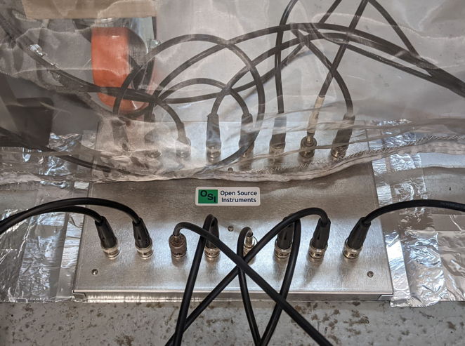
In the photograph above, we see the aluminum sheet floor of the enclosure is taped to the laboratory floor with aluminum tape. The aluminum tape itself is wide, and extends beyond the aluminum sheet by five or ten centimeters. We fasten the feedthrough enclosure so that it lines up with the outer edge of the tape. We secure the enclosure in place by taping its flanges to the floor. The curtain falls naturally between the two sets of cables, where the cables themselves constrain it to lie upon the enclosure, thus grounding the curtain to the enclosure and the floor.

Modifications

[10-MAR-21] The BP2C+ on the A3039C are at risk of being in electrical contact with both the mesh and applied aluminum tape during installation. We will be covering them in clear DP270 Epoxy in order to insulate them electrically.

Development

[06-OCT-20] A303901A and A303902A BNC Feedthrough layouts were submitted for fabrication.

[01-NOV-20] A303901A and A303902A recieved and assembled. Once assembled the complete A3039A is taped with aluminum tape to base of Faraday Enclosure. Board ground and enclosure connected electrically and confirmed with DMM. The two pieces of A3039A are joined mechanically by small pins that are soldered to both the top and bottom boards. They are also grounded together through the same mechanism.

[15-NOV-20] A3039A was left on the floor in its installed state. One of the connectors was stepped on and the solder joints broke. There will need to be future design considerations as the board will be in a similarly installed position when it is shipped to customers. It is also difficult to connect and disconnect BNC cables.

[18-NOV-20] A3039B was submitted for fabrication, it is a RJ45 feedthrough board. The A3039B is comprised of the A303901B connector board and A303902B base board.

[01-DEC-20] A3039B was recieved and assembled using identical through-pin mechanism as the A3039A. Aluminum tape is again used to bind circuit to the Faraday Canopy.


Figure: A3039B with (ACC) enabled through POE connection. The A3039B has been replaced by the A3039F, which provides its own enclosure.

[5-DEC-20] A3039A and A3039B are used to take simultaneous video and EEG measurements using the video and neuroarchiver tools. This demonstrates that they work as feedthrows for use within a faraday enclosure.

[1-FEB-21] We decided on developing a 4-8 BNC Feedthrough A3039C. This circuit will allow us to shrink the size of the board to more easily fit inside the canopy with the IVC rack. It is easier to solder due to the size of the through hole pins on the BNC_V. Since it is a 4-8 one can connect 16 antenna to one octal data receiver.

[25-FEB-21] We have complete an array of tests inside the Faraday Canopy using the A3039A circuit. First we measured reception inside the enclosure with a varying number of MA1 absorbers. We turned on external interference by plugging in an antenna to the command transmitter. Then measured interference power with the canopy open and closed along with reception. The results are of this test are in the table below.

Number MA1 Xmitter 1 Reception Xmitter 2 Reception Interference Power Open Interference Power Closed
4 100.00% 100.00% -42.0dBm -68.5dBm
3 98.54% 99.86% -38.0dBm -61.0dBm
2 98.75% 99.23% -40.5dBm -59.5dBm
1 99.39% 99.73% -40.5dBm -59.0dBm
0 99.89% 100.00% -37.5dBm -52.0dBm
Table: Reception and Interference Power with Varying Number of MA1

[27-FEB-21 ]We ran another set of tests at higher controlled interference using a power boosted command transmitter. Again we varied the number of MA1 in the Faraday Canopy. We can see that at the higher interference values we start to have significant reductions in transmission. The interference power measurements were taken with the canopy opened in the front and closed.

Number MA1 Xmitter 1 Reception Xmitter 2 Reception Interference Power Open Interference Power Closed
4 92.52% 95.88% -24.5dBm -45.5dBm
3 97.82% 98.90% -19.5dBm -41.5dBm
2 92.75% 43.06% -17.0dBm -39.0dBm
1 91.37% 99.59% -22.0dBm -35.0dBm
0 76.01% 88.41% -22.0dBm -32.5dBm
Table: Reception and Interference Power with Varying Number of MA1

[01-MAR-21] We begin testing our (A3035) Implantable Inertial Sensor for Tufts University inside the faraday canopy. We use the coaxial feedthrough for these measurements. We measured transmission with all 4 MA1 absorbers in the enclosure and once with external interference and once without. The IIS is also submerged in water within a fish tank along with the antennas. The antenna is a hand turned 13mm loop of solid core wire. The exact power of the interference was not measured.

Interference Reception
No 98.62%
Yes 83.87%
Table: Reception with and without interference with the (A3035).

[05-MAR-21] We constructed one full A3039C, it was much faster to construct than the A3039A. One issue is that the BP2C+ combiner on the top of the board could potentially be grounded when alumnimum tape is applied. We will cover these in clear DP270 epoxy to insulate them from the alumnimum tape. The A3039C has connectors that are significantly easier to add and remove than the A3039A. The vertical Coaxial Cables also constrain the location of the Faraday Canopy, ensuring its proper placement over the aluminum tape and aluminum floor of the camopy.


Figure: Mesh constrained by vertical coaxial cables.

[10-MAR-21] We measured the power on one side of the splitter to the other of the A3039C. Using a Command Transmitter (A3029) and attenuators we were able to put -30dBm of RF power into one side of the A3039C. The output not being measured was always terminated with 50 Ohm terminator. The measurement error is +-.5 dBm

Device Input Power Output 1 Output 2
A3039C -30dBm -32.5dBm -33.5dBm
Mini-Circuits Power Splitter/Combiner -30dBm -33dBm -33dBm
Table: Versions of the Canopy Feedthrough (A3039).

[10-MAR-21] We tested reception inside the enclosure using the A3039C at high intereference levels. We compared the performance of the A3039C to standard BNC T junctions. Again we used the command transmitter to transmit controlled interference to reduce the reception below our "robust" rate of 95%

Reception A3039C Reception BNC T
67.57% 80.00%
Table: Reception measurements from 4 antenna using A3039C and BNC T

[11-MAR-21] We covered the BP2C+ in DP270 clear epoxy, it cures and covers the surface as well as all of the pins thus insulating it circuit from the tape. Visible in figure 2 below are the connector through pins J18 J19... etc.


Figure 2: A3039C with DP270 Epoxy convering exposed surface mounted components.

[25-MAY-21] We have recieved the A303901D and A303902D circuits for the assembly of the A3039D Ethernet feedthrough. Assembly with through-pins has worked again as with the other feedthrough versions. This appears to be a reliable way to bond two PCBs mechanically. There are two silk screen errors on the A3039D. The A303901D has the part number A303902B and is labelled RJ45 Feedthrough instead of Ethernet feedthrough. The A303902D is labelled as Coaxial Feedthrough instead of Ethernet Feedthrough. We will fully assembly the A3039D circuit shortly.

[16-JUN-21] We have assembled a three A3039D circuits. The connecting pin methods was again succesful in joining the two components, and the new Ethernet connector footprint also works properly.

[28-JUL-22] The A303901ER1 transmission line has a coplanar waveguide with spacing 40 mils and track 30 mils. Its impedance will be roughly 100 Ω. We are now concerned that the feedthrough will cause loss of signal by reflection. We measure minimum SCT power for reception in an A3038DM-C3 detector module with various feedthroughs, including this version of the A3039E. Mr. Sayer reports, "I compared the loss of an RF signal from different feedthroughs. I found that the right-angle BNC feedthrough experienced similar loss to the upright/vertical BNC feedthrough I made recently. Neither experienced a loss of greater than 4dB, both had a loss of around 2 or 3 dB. The combiner however (with a terminator on the unused end) experiences a loss of around 4dB (slightly greater) when bringing through an RF signal. I used both the 905MHz as well as the 918MHz test transmitters and tested multiple tracks on each feedthrough."

We take out the hand-held spectrometer and function generator to measure loss through the feedthroughs. Nathan reports, "Using the handheld function generator and spectrum analyzer, I was able to experimentally determine the loss of an RF signal traveling through our feedthroughs more precisely. I found that our newest feedthough with upright BNCs has a loss of about 1 or 2 dB, and I found the same was true of the right-angle BNC feedthrough that Jordan made. As for the combiner, when terminating one input and putting a signal through the other I also only found a loss of about 2dB. However, when I flipped the combiner around and split the power into one end that was being terminated, I found that I lost 6dB, consistent with how efficient we believe the splitter to be." By "newest feedthrough" Mr. Sayer means the A3039E. By the one that "Jordan made", he means the A3039A, upon which the transmission line is a 7/70 spacing/width coplanar wave guide with impedance close to 50 Ω. We observe no difference between the performance of the 50-Ω and 100-Ω feedthrough impedance.

[29-JUL-22] The 100-Ω impedance of the transmission line on the A303901E should, in theory, cause a wave of 30% the incident amplidue to be reflected off the input and the output. The power of this reflection will be 11% of the total wave. We expect 11% of the wave to go back to the antenna from the input of the feedthrough, where it encounters the 100Ω line, and within the feedthrough, we expect another 11% to reflect from the output connector where the signal enters another 50-Ω line. If all reflected power is lost, we should see 2 dB loss just from these reflections. We already see 2 dB from the connectors of the A3038A, which contains a 50-Ω line, so we might expect a total 4 dB loss through the A3039E. But we see only 2 dB. We note that the length of the 100-Ω line within the A3039E is 100 mm, the speed of the wave on the line is 62% of c, so the 900-MHz wavelength is 206 mm: the 100-Ω line is one half a wavelength long. Be that as it may, the reflected power, regardless of its phase, has only one place to be absorbed: at the antenna's damping attenuator or in the detector module's amplifier. If half goes back and half goes forward we have 1 dB loss due to the error in the A3039E's impedance.

[07-OCT-22] Printed circuit boards for enclosed Ethernet feedthrough are ordered. Enclosure designed.