 BCAM Calibration on a Granite Beam
© 2005-2009, Kevan Hashemi, Open Source Instruments© 2010-2020, Kevan Hashemi, Brandeis University
| OCT-15 | APR-16 | MAY-16 | JUN-16 | |
| AUG-20 |
[10-SEP-15] Here we describe the calibration of BCAM cameras and sources with a flat granite surface and a steel straight edge. By calibration of a camera we mean the measurement of the location of the camera pivot point, the distance between the pivot point and the center of the image sensor, the rotation of its image sensor, and the bearing of pivot point from the image sensor center, all in the coordinates defined by the BCAM mount. By calibration of sources we mean measuring their positions in mount coordinates. We can also measure only the separation of sources on the granite beam, by translating the sources perpendicular to the straight edge, and this simple process turns out to be a valuable check of source calibrations provided by other means.
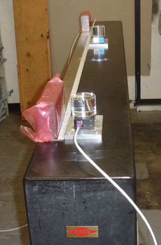
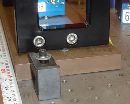
In the photographs, we see a Black Azimuthal BCAM at the far end of the beam. This is the BCAM that we want to calibrate. It is our test BCAM. At the near end is a blue BCAM that we will use to calibrate the black BCAM. It is our reference BCAM. To calibrate the test BCAM camera, we move the reference BCAM along the straight edge, while the test BCAM remains stationary. Our camera calibration procedure uses a pre-existing absolute calibration of the reference BCAM's sources to calibrate the test camera, and a pre-existing absolute calibration of the reference BCAM's camera to calibrate the test sources. When we calibrate the test camera, we move the reference sources from a range of about 50 cm to 150 cm in steps of ten or twenty centimeters. When we calibrate the test BCAM sources, we move the test BCAM along the straight edge and acquire images with the reference BCAM camera.
The arrangement shown above provides 50-μrad absolute accuracy in measuring the y-component of the axis direction, but only 250-μrad accuracy in measuring the x-component of the axis direction. The granite beam is flat to ±2.5 μm, but the straight edge is straight only to ±25 μm. But we can obtain an accurate measurement of the x-component of camera axis direction by rotating the two blocks and setting them down as shown below. This arrangement is inaccurate for rotation and in the y-direction, but as a compliment to the first arrangement, it allows us to obtain accurate measurements of all calibration constants.

In addition to calibrating BCAM cameras and sources, we can also perform some fundamental calibrations of a pair of sources on the granite beam. We translate the sources sideways in known steps with the help of gauge blocks, and in doing so we can measure the separation of two sources precisely, even if we don't have any calibration constants for the viewing camera, and we can measure the difference in their height above the granite surface as well. These two measurements allow us to refine the calibration constants of the reference cameras and sources we use on the granite beam.
In our work with the granite beam, we are comparing the calibration to the ones we obtain with our calibration roll-cage and reference block. In the roll-cage procedure, we rotate the BCAM and take images of the reference sources at two different ranges. We must use a CMM to measure the roll-cage, and we must calibrate the reference sources with the help of a micrometer stage. But we must obtain the rotation of the reference sources with respect to the roll-cage with the granite beam translation measurement. This roll-cage procedure, although complex to set up, is fast, redundant, and reliable. We calibrated over a thousand BCAMs with the roll-cage, and its accuracy and precision we understand well.
The User Manual provides a detailed description of the BCAM and its calibration parameters. We describe the roll-cage calibration procedure, from the point of view of someone performing the procedure, in the BCAM Calibration Manual. We describe how the roll-cage procedure works, and demonstrate its accuracy in our BCAM Calibration ATLAS note. If you are interested in how we assemble BCAMs, please take a look at our Assembly Manual. We read out and control the BCAM electronics using our LWDAQ System. If you would like to know more about the electronics inside one of our Azimuthal BCAMs, look at the A2048 manual.
Our camera calibration and source calibration tools allow us to calibrate cameras and sources on the granite beam respectively.
[18-NOV-15] When a BCAM moves, its light sources move with it, and any camera that happens to take a picture of the light sources before and after the movement will be able to provide us with a measurement of the movement. For any point in an image, there is a unique line along which a light source must lie for its image to be centered upon that point. The position of a light spot tells us the bearing of a light source with respect to the camera, but it does not tell us the range of the light source. Accurate measurements require not only a precise camera, but also that we be able to relate points in the camera image to lines in the global coordinate system of the structure upon which our camera is mounted.
If the camera viewing the point sources has precise and linear optics, then we can make precise and linear measurements of the bearing of a BCAM as it moves through the camera's field of view. We can make a range measurement also, by looking at the separation of the two spots in the image. The farther apart the light spots, the closer the BCAM. But this measurement is far less precise than measurements of movements across the field of view because it's precision decreases as the second power of the range, while the cross-field precision decreases as the first power of the range.
A BCAM provides a camera to look at sources on other BCAMs, and sources that can be looked at by those same BCAMs. By design and construction, a BCAM camera is precise and linear, as we show in The BCAM Camera. Our azimuthal BCAMs, which we developed for ATLAS at the Brandeis University High Energy Physics Laboratory contain a lens with focal length seventy-five millimeters. Behind the lens is a knife-edge aperture two millimeters in diameter. The narrow aperture gives the camera good depth of field. Our standard BCAMs operate at full accuracy from ranges eighty centimeters to infinity. The original BCAM image sensor was the TC255P, but starting in 2014 we started making BCAMs with the ICX424, a larger image sensor with smaller pixels.
When we consider that the optical center of the lens may not lie at its physical center, and that the aperture is one milimeter behind the lens, and that the aperture causes diffraction of the light passing through it, we might wonder at the complexity of the model required to represent the transformation between light spot position on the image sensor and the line upon which its source must lie. But we showed in BCAM Calibration that BCAM optics are equivalent to a simple thin-lens system. If we are to make accurate measurements of light source positions with respect to the structure upon which a BCAM mounts, then we need to measure the geometric properties of the simple thin-lens system to which a BCAM camera is equivalent. We also need to measure the locations of its light sources with respect to the mounting structure.
To calibrate a camera on the granite beam, we move the reference BCAM, with its calibrated sources, towards the test camera. The test camera, you will recall, is the one we want to calibrate. The reference sources move towards the test camera, while the test camera remains stationary. At each position, we know the location of these sources with respect to the test BCAM's chassis. Both BCAMs are mounted upon measured kinematic mounts (which we discuss below). The granite beam is flat, and the straight edge is straight enough. So the sources move in known parallel straight lines and we take images of them with the camera. After several positions, there is only one arrangement of camera lense and image sensor that can produce the observed spots on the test image sensor for the given source positions. After ten positions, we can fit straight lines and obtain a best of the camera geometry.
We could, in theory, calibrate the sources on a BCAM at the same time as we calibrate its camera, by taking images of the sources using the calibrated reference camera. But it is more accurate to leave the reference camera stationary and move the test sources instead. As we move the test sources towards the referenc camera, we take images with the camera and after a few images there is only one location of the sources in the test BCAM chassis that could produce the observed spots on the reference image sensor. After ten positions we can fit straight lines and obtain a best estimate of the source positions.
[18-MAY-16] To make calibration possible, we must provide a reliable kinematic mount for the BCAM chassis and we must measure this mount with 1-μm precision in order to obtain the absolute pointing accuracy we need for calibrating a camera axis bearing to 30-μrad. The BCAM chassis rests on three quarter-inch steel balls. There is a conical depression at the front of the BCAM that receives the first steel ball, a slot at the rear to receive the second, and a flat recession to receive the third. You will find a machine drawing of the chassis here. We hold the BCAM on the balls with a single screw passing through its lid. As we tighten the screw, the ball under the flat depression presses into the aluminum, which is softer than the ball. We tighten the screw with a torque wrench to twenty ounce-inches (0.14 Nm). If we don't have a torque wrench, we finger-tighten the screw and then tighten it by one half-turn more with a wrench. The lid against which the screw presses is flexible enough that the fastening torque increases slowly with turns of the fastening screw, and the stell ball presses into the chassis by about 2 μm when we use the hand-tightening or torque screwdriver.
Once we have calibrated a BCAM one one kinematic mount, our hope is that the same calibration constants will apply on any other BCAM kinematic mount. For this to be true, the steel balls of all the mounts must be of the same diameter as those on the original mount. We buy 6.350-mm diameter (0.250") 316-stainless steel balls with diameter accurate to ±1 μm. We use part number Small Parts, part number BXX-0250-C. In quantity 100, they cost only $0.15 each.
Our current recommendation for tightening by hand is finger-tight plus quater-turn, which gives the same torque as our 0.14 Nm torque wrenches. To speed up our experiments, we sometimes do not fasten our cameras to the camera mount, but instead to press them down with a 700-g weight. We measured the change in calibration constants that took place when we screwed down a camera finger-tight plus one half-turn, which was our recommendation at the time we did our first granite-beam measurements. Over the course of many measurements, such as this one, we found that the camera axis tilts upwards by 20 μrad, and the CCD rotates by roughly 50 μrad. In black BCAMs, axis.y increases by 20 μrad and rotation decreases by 50 μrad. In blue BCAMs, axis.y decreases by 20 μrad and rotation increases by 50 μrad. Given that the shorted distance from the flat ball and the line joining the cone and slot balls beneath a BCAM is roughly 40 mm, a rotation about this line of 50 μrad, which is what we see on the CCD, implies that fastening the screw finger-tight plus half a turn causes the flat ball to sink into the flat depression by 50 μrad * 40 mm = 2 μm.

As we tighten the screw, the axis.y of a blue BCAM drops linearly. In the case of the Blue N-BCAM, the change is −19 μm/90°. In the case of the Blue Azimuthal BCAM it is −11 μm/90°.
[18-NOV-15] In this report, we describe how you can calibrate BCAM cameras and sources using a granite beam and a steel straight edge. Such a calibration system is easier to set up than a roll-cage, and we believe it is also more accurate and faster. To calibrate BCAMs you will need the following.
The BCAM Mounting Blocks have flat bases that sit perfectly on a polished granite table or beam. When we pull them off a flat granite surface, we find that we have to overcome the force of vaccum suction between the block and the granite. The block is rigid and the balls are glued in place, so they do not move with respect to one another. They always sit at the same height above the granite beam. The sides of the blocks are straight, so if you press a side up against a straight edge, the orientation and location of the balls with respect to the straight edge are always the same. This allows us to use a granite table and a steel straight edge to define a global coordinate system in which to move light sources along a known trajectory so as to determine a BCAM camera's calibration constants, or to move a camera along a known trajectory so as to determine the positions of a BCAM's light sources.
We can provide blue and black BCAMs with precisely calibrated light sources. We first calibrate the light sources of such a BCAM in the roll-cage, to determine their position to within 5 μm. Then we place the BCAM on a micrometer stage and move it across the field of view of another BCAM. We know how much we have moved the light sources between images taken by the observing camera, and from this we can deduce the separation of the light sources that corresponds to the separation of the light spots on the image. Next, we put the BCAM on a measured mounting block on a granite table and move it across the field of view of another BCAM. The light sources are moving horizontally, so we can see the horizontal direction defined by their movement in the camera images, and from this we determine the angle between the horizontal and the line joining the two sources. We now refine our the light source positions we measured on the roll-cage so that they are consistent with the actual separation of the sources to 1 μm and their actual relative orientation to 200 μrad.
For data acquisision, we the LWDAQ software is free and runs on Linux, Windows, and Mac OS X. The .
[18-NOV-15] You will find calibration constants for all existing BCAM cameras and sources in the Brandeis University parameter database. The calibration constants are listed according to serial number. These constants were calculated by the LWDAQ program's BCAM Calculator Tool. This program takes measurements made on a BCAM calibration stand and calculates calibration constants. The program supports only measurements made on a roll-cage calibration stand, not the measurements made on a granite beam.
The roll-cage provides six calibrations of a camera, because any two of the four orientations of the roll-cage provide adequate information for calibration. We look at the range of values obtained from the six possible combinations of four orientations, and calculate the average value of each parameter and the spread of values. If the spread exceeds four times our desired calibration accuracy, we reject the calibration. The calibration shown in the figure we performed on a freshly refurbished roll-cage, and the spreads in parameter values are well within our limits.
The cameras have seven calibration constants, which we express in BCAM Coordinates (see the User Manual for details, but in brief: x is across the front of the BCAM, y is vertical, z is along the camera axis, and the origin is at the center of the cone ball). The first three (pivot.x, pivot.y, and pivot.z) give the coordinates of the center of the pivot point of the camera, which is the center of the virtual lens in the virtual thin-lens system to which the camera is equivalent. The next two (axis.x, axis.y, and axis.z) give the direction cosines of the line upon which a light source must lie for its image to be projected onto the center of the camera's image sensor. The z-component of this direction is +1 for all Azimuthal BCAMs, but the Polar BCAM is double-ended, and its rear-facing camera has axis.z equal to −1 as a consequence. We include the axis.z direction in among the seven calibration constants for the convenience of analysis software, but we do not count it as a calibration parameter itself, since we never deduce it by calibration. The sixth calibration constant (ccd-pivot) gives the separation of the plane of the image sensor and the pivot point. The last constant (rotation) gives the rotation of the image sensor about the camera axis.
The figure above shows the BCAM Calculator output for source calibration constants. The roll-cage calibrates the x and y positions of the sources (these are the directions perpendicular to the camera axis), but we assume the z-coordinate just as we assume the axis.z direction in a camera. By construction, the lasers are at z-coordinate 0.36 mm.
Each kinematic BCAM mount defines its own BCAM coordinate system. We use the three ball positins to define the coordinate system in such a way that any BCAM mounted upon with three balls will sit in the same location and orientation with respect to this coordinate system. The calibration constants, which describe the BCAM camera and locate its sources in BCAM coordinates, apply to the coordinate system of any kinematic mount upon which we mount the BCAM.
Suppose we know where the balls of a BCAM mount are with respect to a global coordinate system. Most likely we measured their positions with a CMM. When we take an image of a BCAM light source with a BCAM mounted upon these balls, we can use the BCAM calibration constants to convert the position of the light spot on the camera's image sensor into a line in the coordinates of the mount, and then use the ball positions to transform this line into the global coordinate system. The BCAM measures the direction of this line with a precision of 5 μrad and an accuracy of 50 μrad. It measures the position of the pivot point, through which the line passes, to an accuracy of 20 μrad.
If our camera is observing a pair of light sources on a calibrated BCAM, then we know the separation of these two light sources in the global coordinate system. If we assume that the two light sources are at the same range, which is the case when two BCAMs face one another head-on, we can use our camera calibration constants and the separation of the light spots on the camera's image sensor to measure the range of the light sources. Our uncertainty in measuring the range of two sources is proportional to the square of their range. As they get farther away, the distance between the light spots decreases, so the error in measuring the position of a single light spot becomes more significant compared to the separation we are trying to measure. Furthermore, the fractional change in separation per unit increase in range is inversely proportional to range. We find that azimuthal BCAMs facing one another will give range measurements precise to 300 μm and accurate to 1 mm when the camera has been calibrated on a roll-cage.
[18-NOV-15] To measure the pivot-ccd separation of a BCAM, we the BCAM on the test block and press the left side of the block against the straight edge. On the reference block, we place another BCAM, ideally one that is a mirror image of the test BCAM. We open the Camera Calibration tool and enter the reference BCAM's source calibration constants in the source_positions field. These constants should give the correct separation of the two sources horizontally and vertically. We specify the camera type with the camera_color and camera_nominal fields. The camera_nominal field should contain the nominal calibration constants of the camera. You will find these constants in the comments of the camera calibration script.
We take an image of the two sources on the blue BCAM. Using the camera's pivot.z and ccd-pivot constants, the known separation of the two light sources, and the known distance between the front edge of each mounting block and its cone ball, we obtain a BCAM measurement of the separation of the two blocks, as seen by the steel ruler. Our objective is to compare this measurement with the actual separation, and so check the accuracy of the pivot.z and ccd-pivot constants.
We make sure that the front edges of both mounting blocks lie on a 5-cm boundary on the ruler. Because the nominal pivot.z and ccd-pivot values are close to the actual values, they allow us to determine automatically which multiple of 5 cm separates the two blocks. We obtain our data by moving the blue BCAM block from one 5-cm boundary to another, in any order. Our only constraint is that both the reference sources must be entirely within the field of view of the test BCAM.
At each source position, we calculate the BCAM's measurement of block separation and the steel ruler's measurement of the same separation. We are using We plot the two against one another. The slope will be unity if the nominal ccd-pivot distance is exactly correct. We divide the nominal pivot-ccd distance by the slope to get our measurement pivot-ccd distance. The intercept will be zero if our nominal pivot.z position is correct. We divide the intercept by the slope, and subtract the result from our nominal pivot.z to get our calibration of pivot.z. Below is a plot of the residuals from a straight line fit to the graph of nominal BCAM z measurement against steel ruler z measurement.
In theory, the granite beam measurement of the pivot.z position should be superior to that provided by the roll-cage: we have many more ranges with which to plot the straight line that is required to locate the pivot.z. But the following graph shows that our measurement of pivot.z is dependent upon our choice of calibration ranges.
Using all the above data points, our N-BCAM pivot.z comes out to be −0.7 mm. If we were to use only the first three points at close range, we would get pivot.z at −4.3 mm, which is inconsistent with our observations. The pivot point is at around 0.0 mm in this BCAM. If we use only the points at ranges greater than 750 mm, we get −1.6 mm. Using the central points in ranges 350-700 mm, we get −2.3 mm. The pivot-ccd distance is also sensitive to our choise of calibration ranges. With all the points shown above, we get pivot-ccd of 49.127 mm. Using the first three points we get 50.0 mm, the middle set of points gives us 48.9 mm, and the points farther than 750 mm give us 49.2 mm.
[18-NOV-15] At each range, we measure the difference in height of the two sources on the blue BCAM. We know this difference from our precise calibration of the blue BCAM light sources, so we can deduce the error in the black BCAM camera's rotation constant.
The average height difference measured by the BCAM is one basis for checking the rotation calibration error. But the rotation measurement should be more accurate at close ranges, because the separation of the light spots is greater. On the other hand, we encounter errors caused by the black circle in the light spot at ranges less than 70 cm. Fit a straight line to the rotation of the sources measured at each range from 70 cm to 150 cm. The value of this line at the nearest range is our measurement of the rotation calibration error.
[18-NOV-15] When we measure pivot.z and pivot-ccd, we take images of both reference sources at all ranges. These measurements allow us to calculate pivot.y and axis.y as well. At each range, we use our nominal camera calibration constants to calculate the height of both sources above the granite beam. We take the average of these two heights to represent how the center-point between the sources is moving. We subtract the known center-point height of the two sources, which we have from our calibration of the reference sources. We plot the center-point height error versus range measured by the steel ruler. The slope of this line will be zero if our nominal axis.y is correct. We subtract this slope from the nominal axis.y to get our measurement of axis.y. (If the slope is 0.004 mm/mm, our axis.y is 4 mrad too high.) The intercept of the line with the vertical plane containing the pivot point will be zero if our nominal pivot.y is correct. We subtract the intercept from the nominal pivot.y to get our measurement of pivot.y. (In the case of blue BCAMs, we add the intercept because the blue BCAM y-axis is downwards.) The graph below shows residuals from the straight line fit to the BCAM's measurement of source height versus range.
We should see the shape of the granite beam in the residuals, but what we see at ranges 50 cm to 70 cm is a jump in the BCAM's measurement of source height caused by the appearance of a black circle in the middle of the light spots, as shown in Figure 8.
The edges of the black circle are so sharp that they interact with the borders of the image sensor pixels, and give rise to errors of order 1 μm in our measurement of light spot position. We will continue to report data we obtained from ranges 40 cm to 160 cm, but we are resolved not to use ranges less than 70 cm when we calibrate BCAMs on a granite beam. The slope of the graph we obtained with twenty-three steps from ranges 40 cm to 160 cm was 0.000009, and the intercept was 27.742 mm. These correspond to an axis.y error of 9 μrad and pivot.y error of 28 μm.
We place black N-BCAM A0001 on the test block and blue A-BCAM B0375 on the reference block. We calibrate the test camera for ranges 25-165 cm. At 25 cm the pivot-source range is 300 mm. The left-hand source image is shown below.

The y-direction residuals are shown below versus range.
The standard deviation of residuals is 7.5 μm using all ranges. If we restrict ourselves to 70-150 cm the residuals drop to 3 μm using the same measurements. We repeat the calibration with 10-cm steps from 70-150 cm. The y residual is 4.4 μm. For calibration constants we get pivot.x −10.216 mm, pivot.y 21.624 mm, pivot.z −0.178 mm, axis.x 4.038 mrad, axis.y 2.411 mrad, pivot-ccd 49.200 mm, rotation −11.030 mrad.
[18-NOV-15] The best way to measure pivot.x and axis.x is with vertical blocks. But we will start by using the same data we obtained from our horizontal plane experiment, and make the assumption that the steel straight edge is straight to check the pivot.x and axis.x calibration constants.
At ranges less than 70 cm we have a 10-μm effect from the black circle in the light spots, but at greater ranges, we are seeing the shape of the steel straight edge. The 11-μm residuals are consistent with the straight edge specification of ±25 μm.
The slope of our data is −0.000150, and the intercept is 63.646, which correspond to a pivot.x error of 148 μm and an axis.x error of −150 μrad. But we are, of course, assuming that the camera mounting block is square. Any deviation from square at the front left edge adds directly to the axis.x error we calculate. We are also assuming the source block is four inches wide. Any deviation from four inches adds to the pivot.x error we calculate.
If, instead, we place balls in a vertical plane, the x-direction is now perpendicular to the granite surface. We use the same software and block measurements to obtain the following residuals.
With the vertical blocks, the standard deviation of the x residual is 4 μm, compared to about 20 μm for the horizontal plane.
[19-NOV-15] To calibrate sources, we need a reference BCAM camera for which we know the rotation and pivot position parameters precisely. We mount the reference camera on the reference block, and press its left side up against the steel straight edge. The test sources go on the test block, and we press the right side of the test block up against the steel straight edge. We use horizontal plane orientation to obtain the most accurate measurement of the source y-coordinate and vertical orientation for the x-coordinate. We move the test block along the straight edge. At each point we measure the position of both sources with the reference BCAM camera, which remains stationary. We use the reference camera calibration constants to calculate the source positions. If the measurement of the reference block and the camera calibration constants are accurate, the measured height of the sources above the granite beam will be constant. We moved two sources all the way along the beam and fitted a straight line to the x and y coordinates of the first and second sources. The graph below shows the residuals.
The x residuals are larger, because our precision is that of the steel straight edge. The y residuals are only a few microns rms. Calibration from range 700 to 1500 mm, as we use for camera calibration, gives us a precision of a few microns.
We note that the camera pivot-ccd and axis direction need not be known precisely for this calibration to be accurate. Our procedure measures and compensates for the effect of errors in both these parameters. Knowing the pivot.z to within 1 mm is sufficient. We find that our granite beam measurements are accurate to around 20 μm when compared to roll-cage measurements.
[25-SEP-10] Suppose we had a rectangular aluminum block with two lasers placed symmetrically about its center. We measure the width and height of the block with a micrometer to ±5 μm accuracy. We press this block up against our straight edge so that the lasers are facing the BCAM we want to calibrate. We take an image of the two lasers. We rotate the block by 180° and take another image. The lasers have changed places with one another. Now suppose we knew the magnification of our image, and also the rotation of our image sensor with respect to the granite beam. By comparing the two images, we can determine how far each laser moved horizontally and vertically. We can calculate how far each laser is from the block center, and so we can determine their absolute position with respect to the straight edge and the granite surface. We have the reference sources we need to calibrate our camera.
We assumed that we knew the magnification and rotation of our BCAM image. The rotation of the image we can obtain by moving our block horizontally across the field of view, and perpendicular to the field of view, along the granite table surface. We take images at ten or twenty positions and fit a straight line to get the angle of the image sensor rows with respect to the granite surface. The magnification of the image we can obtain with a gauge block, which is a rectangular block of exact dimensions. Suppose we had a 20-mm gauge block. We insert the block between our source block and the straight edge, so as to move our sources by 20 mm. One of the sources is still in view. We measure how far its image moves across the sensor and we have our magnification.
We applied the above procedure to rectangular blocks that were not symmetric and were not designed for the purpose, and met with good results, as we describe elsewhere. All we need to obtain a pair of reference sources suitable for calibrating a BCAM mounted on a reference block is a gauge block and a granite table.
[22-OCT-15] We want to use a blue azimuthal BCAM to provide reference sources. We plan to start with the roll-cage measurement of its source positions, then correct the separation and rotation of the sources with the help of the granite beam. We put the blue azimuthal BCAM on our reference block (starboard side touching the straight edge) and a black azimuthal BCAM on our test block (port side against straight egde). The front edges of the blocks are separated by 1050 mm on the stright-edge ruler. We take images of one of the reference sources and obtain resolution on the test camera image sensor of 0.05 μm in x and 0.08 μm in y. We re-set the reference block against the straight edge repeatedly and obtain resolution 0.3 μm in x and 0.1 μm in y. We re-set the block against two 20-mm gauge blocks, as shown below, and obtain resolution 0.3 μm in x and 0.1 μm in y.

The magnification of the camera is roughly 1/15 at this range, so 0.3 μm is 5 μm precision in placing the reference block with the balls in a horizontal plane, against the straight edge.
[25-OCT-15] Continuing the above work, we move the reference block in steps of 5 mm with our gauge blocks a total of 35 mm. We fit a straight line to the x and y coordinates of the image position with respect to source displacement. The residuals have standard deviation 0.15 μm in x and 0.20 μm in y. The slope in x is 62.586 μm/mm. The slope of source y-position versus displacement is 0.064 μm/mm. We place a selection of BCAMs on the test block at the same range and measure the separation of the images of their sources. We take ten images of each pair and use the average image separation as our measurement. We use the slope we just obtained to calculate source separation from image separation. Wit the help of a Script 2, we obtain the following table comparing roll-cage and granite beam measurements.
The calibration of B0425 is poor: source separation from roll-cage is 44 μm too small. We select B0375 to provide reference sources. The roll-cage source calibration is 12 μm too large, so we edit the roll-cage measurements and bring them both 6 μm close to one another. The height difference between the first and second source is 24 μm too low. We move the first source up by 12 μm and the second source down by 12 μm. The rotation and separation of the sources is now correct. We are still trusting the roll-cage for the location of the center point of the two sources.
[29-OCT-15] We check the resolution of our horizontal-plane granite beam measurement by placing the same blue BCAM on the camera block ten times, and positioning the block each time against the straight edge. We use nine positions of a black BCAM on the source block, from ranges 70 cm to 150 cm. We avoid nearer ranges to avoid errors caused by the black circle in the light spots.

Our resolution in the y-direction is 3 μm in the pivot position and 3 μrad in the axis direction. In the x-direction, however, the resolution is 19 μm and 32 μrad. The granite beam performs well in the y-direction because this is the direction perpendicular to its flat reference surface. In the x-direction, our reference surface is the steel straight edge. We perform the same experiment, but with a different blue azimuthal BCAM at every step. We compare the roll-cage and granite beam calibration constants at each step.
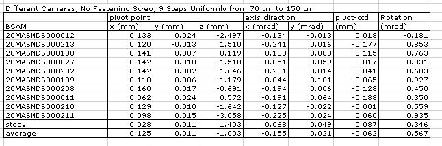
We believe the absolute accuracy of the roll-cage measurement is better than 20 μm rms in pivot position and 50 μm rms in axis direction. Here we see the average disagreement between the granite beam and the roll-cage in the y-direction is only 11 μm and 21 μrad. In the x-direction, however, the disagreement is 125 μm and −155 μrad. The standard deviation of the disagreement, however, is 28 μm and 68 μm. It looks to us as if the straight edge is introducing a constant error in the x-direction.
With the balls in a horizontal plane, we screw down a black azimuthal test BCAM and a blue azimuthal reference BCAM, number B0375. We obtained our reference source positions by starting with the roll-cage calibration of B0375, then correcting the separation and height difference after moving the sources with gauge blocks on the granite beam.
Agreement in pivot.y and axis.x is good. We don't expect good agreement in pivot.x or axis.x when we use the horizontal plane. Agreement in rotation and pivot-ccd is also good. But the pivot.z of the roll-cage measurement is 2.6±0.3 mm too low.
The vertical plane arrangement requires that we fasten each BCAM in place with a screw. We fasten blue azimuthal BCAM number B0375 to the reference block. We adjust the roll-cage calibration constants so as to correct the separation and rotation of the sources as we observed when sliding them across the beam. We calibrate ten black azimuthal cameras for ranges 70-150 cm in 10-cm steps. We reject any calibration with residuals more than 10 μm. We repeat two calibrations because pivot.x differed from the roll-cage pivot.x by more than 50 μm. Our average residual was 4 μm rms, but one run had residuals 1.2 μm.
On average, the roll-cage measurement of pivot.x is 10 μm higher than the granite beam, and of axis.x is 19 μrad higher.
[07-APR-16] We enhance the camera calibration tool to support black and blue N-BCAMs. In particular, we account for the fact that the N-BCAM camera image is the right way up, in contrast to that of the Azimuthal BCAM, which is upside down. We have two rotatable mounting blocks with initial measurements made at the front-right corner. We translate the x-coordinates of the balls so as to obtain coordinates with respect to the front-left, which is what we assume in our calibration code. We calibrate ten black N-BCAMs using the sources of Blue Azimuthal BCAM B000375. We mount the N-BCAM on Block 1 and the Azimuthal BCAM on Block 2. We start with the block in the horizontal direction.
The average difference between the roll-cage and granite beam is only 5 μm in pivot.y and 1 μrad in axis.y. The standard deviation of the difference is 38 μm and 40 μrad respectively. Given that the precision of our granite-beam measurement is 3 μm and 3 μrad, and the precision of the roll-cage measurement is similar in magnitude, we suppose that the standard deviation of the difference is due to a systematic disagreement between the two ways of measuring calibration constants. We repeat with the block rotated so that the N-BCAM mounting balls are in a vertical plane over the ruler edge.
The average difference in pivot.x is −35 μm and in axis.x is 59 μrad, both of which are significant.
[13-APR-16] We re-measure the blocks, this time using the front-left corner as the origin. The axis.x increases by 81 μm, which improves our average difference to −22 μm. The pivot.x increases by 25 μm, which worsens our average difference to 60 μm. We trace this change to a 36-μm increase in the x position of the reference camera cone ball. The left and right sides of the mounting blocks are not perpendicular to the granite surface. In the second block, which is the reference mount, the left and right sides diverge at 1.4 mrad, so the top is 69 μm wider than the bottom, while in the first block, which is the test mount, they converge at 1.2 mrad, so the top is 60 μm narrower than the bottom. We make sketches and attempt to recover our absolute knowledge of the cone ball in the vertical orientation using the block surface orientations. We conclude that we should drop the test camera cone ball by 12 μm and raise the reference camera cone ball by 8 μm, which reduces the average difference in pivot.x to 40 μm.
[06-MAY-16] We choose black N-BCAM A0080 and blue N-BCAM B00005 to be reference cameras. We move B00005 35-mm in 5-mm steps with our gauge blocks. The separation of B00005's sources is 15.983 mm, compared to 15.981 mm as measured by the roll-cage. The locus of the two images makes an angle of −5.532 mrad with the image y-axis. Looking at the ball positions in mounting block No1, the camera is rotated by 14 μm / 42 mm = 0.33 mrad about the mount coordinate z-axis. The rotation of the camera image sensor is 5.194 mrad, compared to 4.652 mrad as measured by the roll-cage.
According to the granite beam, the left-hand source (or "second source" in the roll-cage calibration, or "source element four" in the data acquisition software) is 14 μm above the other. We perform a granite beam source calibration at ten ranges and obtain "−18.461 −21.603 −2.445 −21.609", in which the second source is 6 μm higher than the first (blue bcam mount coordinates have the y-axis pointing down). The current roll-cage calibration is "−18.504 −21.618 −2.523 −21.493 −0.640", in which the second sourc is 125 μm below the first.
The rotation parameter in the Blue N-BCAM source calibration apparatus description is currently −0.65 mrad. We vary it over a range of values to see how the roll-cage calibration is affected.
There is no value of apparatus rotation that reduces the difference between the roll-cage and granite beam to zero.
[09-MAY-16] We bring the roll-cage reference camera to the granite beam and take images of two sources as we move them with gauge blocks. The rotation of the field of view with respect to the granite table is 0.231 mrad. The left-hand source is 16 μm above the other, which agrees well with our earlier measurement of 14 μm with the same procedure.
[10-MAY-16] We calibrate the sources of ten Blue N-BCAMs on the granite beam and compare to their roll-cage calibrations.
We repeat the calibration of B00005 on the roll-cage and obtain from the BCAM Calibrator tool the values "−18.506 −21.620 −2.521 −21.497", which is within a few microns of the original values from the BCAM Calculator. With the roll-cage in its 0° position, the line from the left to right sources makes an angle of −12.5 mrad to the image rows. We stare at the front of the roll-cage.
The base plate sits on three pads. Two are on the back end, one at the center of the front end. We clamped the plate so that it rotates about the pad. With a feeler gauge we estimate the rotation of the plate is 5-6 mrad. We take an image of the two sources with the base plate clamped as above. We move the clamp so that it pressed down directly on the pad. We take another image. The line from the left to right sources now makes an angle of −4.7 mrad with the image rows. The roll-cage base plate has rotated about its z-axis by −7.83 mrad. We change the rotation parameter in the roll-cage apparatus description from −0.65 mrad to −8.48 mrad. We re-calculate roll-cage calibration constants and compare to granite beam. On average, the first source is 27 μm lower when measured by the roll-cage, and the second source is 35 μm lower. The two calibrations agree on the relative height of the two sources to within a few microns.
We rotate the quad source block source positions by −7.83 mrad in the apparatus description for the roll-cage Blue N-BCAM camera calibration. The x-coordinate of the pivot point moves 100 μm closer to its nominal position, and the CCD rotation turns 7.83 mrad closer to its nominal value of π.
[11-MAY-16] We re-calibrate B00005 on the roll-cage and compare the previous roll-cage calibration with the now-updated BND8 apparatus description and the new calibration with the BND9 description.
ver   s1.x    s1.y    s2.x   s2.y
BND8 -18.398 -21.571 -2.416 -21.571
BND9 -18.400 -21.574 -2.417 -21.576
The difference is well within the precision of the roll-cage measurement, so we believe our BND8 source calibrations are accurate. The B00005 camera calibration differs by 50 μrad in axis.y. We re-calibrate all ten of our cameras with BND9 in the roll-cage and obtain the following comparison of the BND8 and BND9 constants.
The rotation of the image sensor agrees to within 117 μrad, which means we have corrected for the rotation of the base plate correctly. The standard deviation of the change in axis.x and axis.y are around 60 μrad, which is double the precision of a our roll-cage measurement with the plate clamped correctly. The average difference is also 60 μrad, which is significant, and suggests a systematic error resulting from poor clamping. No rotation of the roll-cage about the y or z directions can cause a change in either pivot position or axis direction. (We move the coordinates of the BCAM mount cone ball up by 14 μm in all four orientations in the BND8 apparatus description, as might occur with rotation of the base plate about the y-direction. We see no change in calculated pivot position or axis direction.) Nor does rotating the quad source block positions affect the axis direction. (We undo the −7.83 mrad rotation correction of BND8 and get the same axis direction.)
[12-MAY-16] We translate a pair of Black N-BCAM sources across the field of view of B00005. According to the translation, the separation of the two sources is 16.0005 mm. We correct the scaling factor in the N-BCAM source apparatus descriptions, from 26.042 to 26.017. Now the roll-cage measurement of the separation is 15.999 mm. In correcting the magnification, we see both source move up by 13 μm, and sideways by 20-30 μm. The Black N-BCAM sources are far from the axis of the roll-cage, so scaling and rotation are prominent in the calculation of their position. According to the translation, the right-hand source (or "second source" in the roll-cage calibration, or "source element four" in the data acquisition software) is 130 μm above the other. According to the roll-cage, the right-hand source is 128 μm above the other.
[16-MAY-16] We calibrate our ten Blue N-BCAMs on the granite beam and compare constants to those of the roll-cage apparatus BND9.
If we remove B00005 and B00009 from the set, we get an average difference in axis.y of 15 μm and standard deviation 26 μm. We re-calibrate B00005 and B00009 on the roll-cage and obtain axis.y within 10 μrad. The rotation of the image sensor varies from −6 mrad to +16 mrad with respect to its nominal value of π rad. We make a scatter plot of the difference in axis.y versus the rotation but see no pattern. We note that the flat depression under our Blue N-BCAMs has visible marks where we have tightened the mounting screw finger-tight plus half a turn. These depressions are larger than those made when we tighten with the 20 oz-in torque wrench. The depressions are 0.5 mm in diameter, their depth should be 10 μm.
[18-MAY-16] We calibrate B00005 weighed down by 700 g and screwed-down finger-tight plus a half-turn. Screwing down the BCAM decreases axis.y by about 40 μrad We place our set of ten Blue N-BCAMs on one block, weighed down each time, and take images of one laser at 1500 mm, and chosen so that it is close to the center of the field of view. We take the image locations and calculate the source locations assuming nominal values for pivot-ccd and rotation, and roll-cage values for pivot.y and axis.y. Standard deviation of calculated source height is 50 μm. With granite-beam constants the standard deviation is 100 μm. We replace granite-beam pivot.y with roll-cage pivot.y and still get 100 μm. It is the granite-beam calibration of axis.y that is in error.
We calibrate all ten of our Blue N-BCAMs on the granite beam without screwing them down, but holding them only with a 700-g weight. We compare roll-cage to these new constants and obtain far better agreement than with screwed-down BCAMs. The axis.y of B00005 has dropped by 181 μrad.
We take B00005 and mount it with a screw that is finger-tight with an allen key. We obtain this plot, in which the axis.y drops by 19 μm/90°. We tighten a screw finger-tight and then farther with a 0.14 Nm torque wrench. It turns by another 90°. Our rule for tightening by hand should be "finger-tight plus quarter-turn" instead of "finger-tight plus half-turn". Comparted to the roll-cage, we expect the weighted measurement to be 19 μrad higher, and this is exactly the case in the above table.
We examine residuals to the y-coordinate fit for all ten BCAMs and note that in some cases, the nearest-range point, at 60 cm, has residual far higher than the rest. We re-calibrate B00005 on the granite beam with ranges 70-150 cm and the screw finger-tight plus half-turn. We get axis.y of −1.204 mrad compared to our previous −1.337 mrad when we used the 60-cm range in place of 150 cm.
[19-MAY-16] The disagreement in the average pivot.y we observed yesterday cannot be explained by the precision of the granite-beam or roll-cage procedures. One explanation for the disagreement is that our A00080 Black N-BCAM source calibration is 42 μm too low, so that the apparent height of the camera pivot point is lower, which means we obtain a less negative value for pivot.y in a blue BCAM. We take out Black Azimuthal BCAM A000348 and retrieve its roll-cage calibration constants. We use these to calibrate our ten Blue N-BCAMs once again on the granite beam.
Our pivot.y calibration is now 18 μm lower, compared to 42 μm higher. But axis.y is now 41 μm higher, when it should be 19 μm higher. An axis.y error of +22 μrad will give us a pivot.y error of roughly −22 μm, because these two measurements are the slope and intercept of a straight line, and the average range of our measurements is 100 cm. Our pivot point measurement could be correct except for an error in our granite-beam measurement of axis.y. We turn a fan on the granite beam surface and repeat our ten calibrations. We obtain much the same results, with −44 μrad disagreement in axis.y and +24 μm in pivot.y. Looking at our calculations of the effect of thermal gradients, we do not expect thermal layers to have an effect of order 40 μrad along a 2-m beam.
[19-MAY-16] We translate A000348 on the granite beam while viewing with B00025, and repeat several times. We measure the B00025 image sensor rotation about the No1 block z-axis to be −5.5 mrad. Looking at the standard deviation of our residuals, and combining our five measurements, we estimate a precision of 0.2 mrad rms. The No1 mounting balls rotate the BCAM by +0.33 mrad about the the same axis. The rotation of the image sensor in mount coordinates is −5.9 mrad. The calibration of the camera rotation should be 3135.7 mrad. The roll-cage gives us 3134.6 mrad. The translation tells us the sources are 15.985 mm apart. The roll-cage calibration says the sources are 16.006 mm apart. The translation tells us the second source is 0 μm lower than the first. The No2 block rotates the source BCAM by 0.36 mrad about the mount z-axis, which raises the second source by 5 μm. The second source should have black mount y-coordinate 5 μm lower than the second. The roll-cage tells us the second source y-coordinate is 8 μm higher than the first.
[23-MAY-16] We screw down B00025 and move A00080 across its field of view on the granite beam. Our resolution in measuring rotation is 0.1 mrad rms. We obtain −6.0 mrad for the image sensor rotation with respect to the granite beam, from which we subtract the No1 block rotation of 0.33 mrad to get −6.3 mrad. The calibration of the camera rotation should be 3135.3 mrad. The roll-cage says 3134.6 mrad. The second source is 131 μm higher than the first. The roll-cage says 141 μm. We change the rotation parameter in the Black N-BCAM roll-cage BND8 apparatus description. We drop it from 0.806 mrad to 0.20 mrad. We re-calculate the roll-cage BND8 calibration. The first source moves up by 19 μm and the second source moves up by 9 μm, so that the second source is now 131 μm above the first. Our translation on the granite beam suggests source separation 15.998 μm. The roll-cage says 16.000 mm.
We conclude that the correct value for the rotation parameter for roll-cage Black N-BCAM calibration is 0.21 mrad in BND8. We must use the same value for the Blue N-BCAM BND9, and the Blue N-BCAM BND8 will be 7.83 mrad lower due to the erroneous clamping of the base plate. We make these adjustements to the apparatus database and find that our Blue N-BCAM sources have moved by roughly 5 μm. The rotation parameter has a smaller effect upon the Blue N-BCAM calibration because the Blue N-BCAM sources are closer to the roll-cage axis than those of the Black N-BCAM.
We use the latest roll-cage calibration of the A00080 sources to calibrate B00005 on the granite beam. Both BCAMs are screwed down. We compare our calibration to that of the roll-cage for B00005 with BND9 apparatus. Our axis.y is 42 μrad more negative and our pivot.y is 54 μm less negative. We edit the No1 block ball positions, making them all at equal height above the granite table. We re-calculate our granite-beam axis.y and find it has dropped from −1.209 to −1.264 mrad. The No1 block holds the BCAM facing upwards by about 55 μrad, so when we ignore the block rotation, we assume axis.y points more upwards.
[26-MAY-16] We calibrate the A00080 (Black N-BCAM) camera with the B00005 sources. Our axis.y is 3.372 mrad, with residuals 1 μm. The roll-cage says 3.386 mrad. Our pivot.y is 21.650 mm, and the roll-cage says 21.707 mm. We calibrate A000348 (Black Azimuthal BCAM) with the B00005 sources. Our axis.y is 3.594 mrad with residuals 4 μm. The roll-cage says 3.580 mrad. Our pivot.y is 13.142 mm, and the roll-cage says 13.174 mm. We calibrate the A00080 camera with the B000375 (Blue Azimuthal BCAM) sources. Our axis.y residual at range 70 cm is over 20 μm. We calibrate at all possible ranges on our beam and plot residuals.
Using the full set of ranges we get axis.y 3.360 mrad and pivot.y 21.719 mm. We calibrate A00080 again with B000375 using ranges 80-150 cm. We get axis.y 3.363 mrad and pivot.y 21.709 mm.
For both black cameras and both blue sources, our granite-beam axis.y values are consistent with those of the roll-cage. But our pivot.y values are consistent only when we use Blue Azimuthal BCAM sources. When we use Blue N-BCAM sources, our pivot.y moves down by 50 μm. We enhance our camera calibration script so that it will tell us where the test camera measures the sources to be, and where the source calibration says the sources should be. We use our granite-beam calibration constants for the test camera. We measure the location of Blue Azimuthal BCAM sources, then Blue N-BCAM sources. We measure the left-hand source to be 110 μm lower than the roll-cage, and the right-hand source only 3 μm lower. The mid-point between the two sources, which is what the granite-beam calibration uses to obtain pivot.y, is too low by about 50 μm.
[27-MAY-16] We translate B00005 in front of A00080. Our residual in x on the image sensor are 16 μm, which suggests source translation residuals of 300 μm. We repeat the translation and note that is it easy for us to put our 10-mm gauge block in the wrong way around, because it is almost square. We make sure we place the block corectly. We get residuals 3 μm in x on the image sensor. Separation of the sources in x is 15.960 mm and in y is 11 μm. We re-calculate our Blue N-BCAM source calibration and find that the latest BND9 values don't match the ones we are using in our camera calibration program. We update our Blue N-BCAM constants. The roll-cage separation in x is now 15.968 mm and in y is 12 μm. We repeat our granite-beam calibration of A00080 with the corrected roll-cage source positions for B00005. Our axis.y is 3.371 mrad with residual 2 μm. Our pivot.y is 21.684 mm, which is only 23 μm below the roll-cage value. We have agreement between the roll-cage and granite beam for Black N cameras, Black Azimuthal cameras, Blue N sources, and Blue Azimuthal sources.
We use the A000348 (Black Azimuthal) sources to calibrate the camera of B000375 (Blue Azimuthal). Our axis.y is −2.581 mrad with residual 3 μm. The roll-cage says −2.195 mrad. We calibrate B000270 (Blue Azimuthal). Our axis.y is −6.182 mrad. The roll-cage said −6.171 mrad in 2007 with BND7 and −6.138 mrad in 2015 with BND7. The B000375 camera is not among those for which we compared roll-cage and granite-beam calibrations last October. We assume its camera has lost calibration. We have agreement between roll-cage and granite beam for Black Azimuthal sources and Blue Azimuthal cameras.
[06-JUN-16] We use the A000348 (Black Azimuthal) sources to calibrate the camera of B000025 (Blue N). Our axis.y is −1.723 mrad compared to −1.748 mrad with BND9 on the roll-cage. The pivot.y is −21.728 mm compared to −21.698 mm with BND9 on the roll-cage. We use the same sources to calibrate the camera of B00005 (Blue N) without screwing the camera to its mounting block. We get axis.y −1.127 mrad and pivot.y −21.749 mm. We screw the camera down and repeat. We get −1.169 mrad, compared to −1.77 mrad with BND9 on the roll-cage. Our pivot.y is −21.742 mm compared to −21.709 mm on the roll-cage. We have agreement between Black Azimuthal sources and Blue N cameras.
We use B00005 (Blue N) to take images of the A000348 (Black Azimuthal) sources, then the A00080 (Black N) sources at the same range. We project the source positions into global coordinates. The first Black N source is 8.487 mm above the first Black Azimuthal source. According to the roll-cage, the difference should be 8.415 mm. The second Black N source is 8.601 mm above the second Black Azimuthal source. According to the roll-cage, the difference should be 8.538 mm.
[08-JUN-16] We use our B00005 (Blue N) camera with its roll-cage calibration constants to view the A00080 (Black N) sources on the granite beam. We use the granite beam to measure the source positions. We measure the second source to be 178 μm higher than the first. With the roll-cage we measure 131 μm. Our 06-JUN-16 projections place the second source 134 μm higher than the first. We translate the sources across the field of view of B00005's camera and find the second source to be 126 μm higher than the first. The center-point of the two sources is at 21.696 mm with the granite beam and 21.641 mm with the roll-cage. We view the A000348 (Black Azimuthal) sources and move them along the granite beam. The mid-point of the two sources is 13.090 mm. According to the roll-cage, the mid-point is at 13.164 mm. The granite beam places the black N sources 55 μm higher than does the roll-cage, but it places the black azimuthal sources 74 μm lower than the roll-cage.
[09-JUN-16] We discover that our Source Calibration and Camera_Calibration tools are sharing procedure and global variable names. We correct these problems. Both tools are now independent. We now perform source and camera calibrations on the granite beam with the camera on the left and the sources on the right. We add a Transverse command to the source calibration tool so we can analyze results of gauge block translations without cutting and pasting into a spreadsheet.
We translate A00080 (Black N) sources in front of the B00005 (Blue N) camera. The separation of the sources is 15.991 mm horizontally and 125 μm vertically. Our roll-cage says 16.000 mm and 131 μm. The translation suggests image sensor rotation 3156.6 mrad while the roll-cage says 3155.9 mrad. The translation suggests pivot-ccd distance 48.976 mm, while the roll-cage says 48.900 mm.
We observe that our source calibration and our camera pivot point calibration is more accurate if we use short ranges, while our camera axis calibration is more accurate if we use longer ranges. We calibration the A00080 (Black N) sources using the B00005 (Blue N) camera for ranges 30-70 cm. The first source y-position is 21.616 mm compared to 21.575 mm according to the roll-cage. The second source y-position is 21.725 mm compared to 21.706 mm. We use the same measuremenst to obtain pivot.y of −21.679 mm compared to −21.709 from the roll-cage. We use ranges 70-150 cm to calibrate the B00005 (Blue N) camera with the A00080 (Black N) sources. We get axis.y of −1.287 mrad compared to −1.177 mrad for the roll-cage. We try B00006 (Blue N) at ranges 80-150 cm and get axis.y −2.772 mrad compared to −2.661 mrad. We try B000270 (Blue Azimuthal) and get axis.y −6.239 mrad compared to −6.138 mrad. We try B00005 (Blue N) again, after cleaning the bases of both blocks and polishing on the beam. We get axis.y −1.270 mrad compared to −1.177 mrad. The granite beam has the axis angling upwards by 93 μrad compared to the roll-cage. We rotate our blocks and repeat with ranges 30-130 cm. We get pivot.x −10.447 mm compared to −10.418 mm. We get axis.x 1.277 mrad compared to 1.207 mrad. The granite beam has the axis angling upwards by 70 μrad compared to the roll-cage.
We have agreement between the roll-cage and granite beam for Black N-BCAM source positions, and for Blue N-BCAM pivot positions. We do not have agreement for Blue N-BCAM nor even Blue Azimuthal BCAM axis direction, which is wrong by roughly +80 μrad upwards in mounting block coordinates.
[13-JUN-16] We clean the granite beam. We calibrate the camera of B00005 (Blue N) with the sources of A00080 (Black N). We go from 20-1500 cm in 5-cm steps. Our residuals in the y-direction vary from −25 μm to +15 μm for ranges 20-60 cm, see here, suggesting poor performance of the camera at close ranges.
The pivot.y is −21.686 compared to −21.709 for the roll-cage. The axis.y is −1.284 mrad compared to −1.177 mrad for the roll-cage. We calibrate the camera of A00080 (Black N) with the sources of B00005 (Blue N) from ranges 80-150 cm. The pivot.y is 21.689 mm compared to 21.707 for the roll-cage. The axis.y is 3.423 mrad compared to 3.386 mrad for the roll-cage. The axis.y is angling upwards by 37 μrad. We exchange the source and camera positions and repeat for ranges 20-150 cm. We obtain the following residuals, which show the shape of the granite beam to a few microns.
Even at range 20 cm, the Black N-BCAM is accurate. The usual location of the camera block corresponds to ranges 300-400 mm in the plot. At this location, the granite beam appears to have a downward slope of 10 μm in 150 mm = 70 μrad, which is consistent with our systematic error in measuring axis direction.
The image sensor in the camera of B00005 (Blue N) is dirty: a hundred flecks of dust an a few fibers. We clean and repeat our earlier measurement of this camera's y-residual, but obtain almost identical results. This camera performs poorly at close ranges. The lens holder is 2.35 mm back from the front face of the BCAM. In A00080 (Black N) the lens holder is 2.16 mm back. In B00025 (Blue N) we have 2.36 mm.
We move our straight edge so that we use a different portion of the granite beam for our camera block. We calibrate camera B00008 (Blue N). The lens holder is set back by 2.10 mm. For ranges 20-150 cm we obtain pivot.y of −21.705 mm compared to −21.716 mm on the roll-cage. The axis.y is +0.439 mrad compared to −0.436 mrad on the roll-cage. The y-residuals are 20 μrad for ranges below 80 cm and 2 μm above 80 cm. We calibrate again, this time using only ranges 120-150 cm in 5-cm steps. We get axis.y of −0.420 mrad and pivot.y of −21.711 mrad. We study our camera calibration script. We discover an error in the way we handle the original copy of our measurements during analysis. We correct this error.
We calibrate camera B00008 (Blue N) again, at ranges 20-150 cm in 5-cm steps. We get pivot.y and axis.y of −21.687 mm and −0.435 mrad compared to −21.716 mm and −0.436 mrad on the roll-cage. If we use only ranges 120-150 cm (seven points) we get −21.711 mm and −0.420 mrad respectively. We have agreement between the roll-cage and granite beam for Blue N-BCAM cameras and Black N-BCAM sources.
We have solved two problems: using a poor section of the granite beam for our camera block, and garbling our measurements with repeated executions of our analysis routine. Despite dirt on image sensors and poor resolution at close ranges in our Blue N-BCAM cameras, we obtain agreement to within 20 μm rms and 40 μrad rms between the roll-cage and granite beam for all Azimuthal and N cameras and sources.
[28-AUG-20] We have been measuring the separation of optical fiber sources on the granite beam, and comparing our measurements to those made on a CMM. The sources are 2.5-mm diameter zirconia ferrules with the polished tip of the fiber centered to within a few microns and flush with the ferrule face. We measure the separation of the ferrules on the CMM, then translate the sources across the beam to measure the same separation. Each plate has four sources, two on each end. Each pair is separated by a nominal 60 mm.
We use the same apparatus to measure the separation of N-BCAM sources, with nominal separation 16 mm.
We rotate the N-BCAM source mounting block so that we have the two sources separated vertically and we translate them horizontally. The agreement between the granite beam measurement in both orientations tells us that the image sensor pixels are square.
The separation measured by our granite beam procedure is 0.05% smaller than the separation measured by our CMM, in the case of the optical fiber sources, or our roll-cage, in the case of our BCAM sources. Because the roll-cage is measured by our CMM, the movement of the sources during roll-cage calibration are also specified by the CMM. But when it comes to the length and direction of the vector joining two soures, the roll-cage apparatus measurement contains these two parameters:
0.21 {mrad viewing_x_direction}
26.017 {mm/mm viewing_scale}
We set these two parameters so that the roll-cage calibration matches the granite beam calibration. The fact that the Blue N-BCAM roll-cage calibration does not agree with the granite beam is because the viewing scale is 0.05% too small. The disagreement between the direct CMM measurement of the 60-mm source plates and the granite beam is an independent phenomenon.