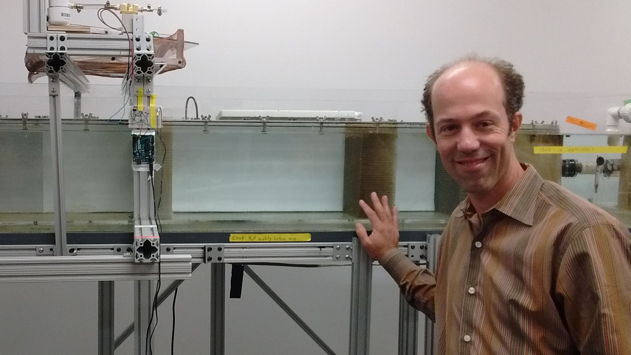
Figure: Professor Eric Tytell Standing In Front of the Swimming Tank.
[29-OCT-19] This work has been funded by the NSF and carried out in collaboration with the Tytell Laboratory of Tufts University.
Open Source Instruments Inc. (OSI) proposes to develop, in collaboration with the Tytell Laboratory of Tufts University (TLTU), a fully-implantable, wireless inertial sensor small enough to implant in the abdomen of a 500-g fish, or suture to the epidermis of a 200-g fish. The Implantable Inertial Sensor (IIS) will transmit accelerometer and gyroscope inertial measurements at a minimum of 100 Hz for a minimum of eight hours while its host fish swims in an aquarium equipped with antennas to receive the telemetry signals. The IIS will be equipped with a rechargeable battery that will provide the minimum eight hours of operating life at least ten times before the performance of the device is compromised by circuit corrosion or battery wear.
| Property | Value |
|---|---|
| Maximum Displacement Volume | 0.6 ml |
| Maximum Outer Dimensions | 16 × 11 × 3.7 mm3 |
| Maximum Weight | 1.0 g |
| Minimum Transmission Range | 100 × 30 × 30 cm3 |
| Maximum Final Device Cost | $500 US in QTY 10 |
| Minimum Gyroscope Performance | ≥100 SPS, 16-bit, 3-axis |
| Minimum Accelerometer Performance | ≥100 SPS, 16-bit, 3-axis |
| Nominal Battery Capacity | 11 mA-hr |
| Minimum Operating Life | ≥8 hr |
| Maximum Recharge Time | 72 hr |
The IIS will be designed to be used and recharged at least ten times. It may be recharged to full capacity in seventy-two hours using a voltage source, a series resistor, and two specially-designed clips that attach to the recharging loops on one end of the device. The useful life of the device will be limited by the resilience of its leads and encapsulation. We will guarantee the device against manufacturing defect, fatigue failure, or corrosion damage for one year after delivery. To turn on and off the device, we will use a magnet, which activates a magnetic sensor on the device to change its state from on to off, or from off to on.
The IIS uses the same radio-frequency telemetry and power-saving system as OSI's established Subcutaneous Transmitter (SCT) system for recording EEG in mice and rats. The only significant difference between the operation of the telemetry in air and in water is that the water-resident antennas are five times shorter, and that the water-based system does not require a faraday enclosure to reject local radio-frequency interference. The water itself absorbs reflects roughly half of interference incident upon the outside of the aquarium, and attenuates penetrating radio waves by a factor of ten within ten centimeters. Thus the water acts as a natural isolation chamber for the telemetry, while the telemetry system in air for mice and rats must be enclosed an isolation chamber made of steel mesh and foam absorbers.
The inertial measurements provided by the IIS will be recorded to disk using the open-source LWDAQ Software. The existing Neuroplayer Tool of the LWDAQ Software allows us to examine and analyze the inertial recordings. The existing Videoarchiver Tool will allow us to navigate through video recordings of the swimming fish and view simultaneous inertial recordings with a single mouse-click.
Professor Eric Tytell of the Tytell Laboratory, Tufts University studies the biomechanics and neural control of swimming in fishes. They have been measuring the acceleration and rotation of fish swimming against a water current using an accelerometer sutured to the epidermis of the fish, and connected to a data acquisition system and power supply by flexible wires, as presented here. The wires do a good job of providing power and reading out the sensor at any desired sample rate, but they interfere with the movement of the fish, compromising the integrity of the study.
At OSI we have been making implantable wireless EEG monitors for over a decade. We describe our original devices in A novel telemetry system for recording EEG in small animals (2011). In the past year we released our smallest device to date, the Subcutaneous Transmitter (SCT) model A3028T1-R for monitoring EEG in mouse pups. Its volume is only 0.5 ml and its rechargeable battery provides a minimum of 160 hours of sixteen-bit EEG recording at 128 SPS.

We propose to substitute an accelerometer and gyroscope for the EEG amplifiers and sixteen-bit converter of our SCT circuit, and transmit sixteen-bit rotation and acceleration measurements in place of sixteen-bit EEG voltage samples. Referring to the photograph above, we will remove the EEG leads leave the 13-mm antenna, and add three steel rings half-buried in the epoxy encapsulation to allow the researcher to suture the device in place.
Equipped with the IIS rather than a tethered sensor, the fish will now be able to swim freely in the tank, its rotation and acceleration measured by the wireless implant. Indeed, it will now be possible to have several fish swimming together in the same tank, and monitor all their movements simultaneously with separate implanted IIS devices, or monitor only a few of them while they swim in a larger school. Our LWDAQ Software, Neuroplayer Tool, and Videoarchiver Tool will combine the inertial and video recordings to permit navigation and examination, or to automate exporting of the inertial recordings into a format preferred by the researcher.
The IIS will consists of the following components.
The IIS circuit will be smaller than the circuit required by the A3028T1-R, because it will contain no EEG amplifier and no ADC outside those provided by the tiny accelerometer and gyroscope devices. The battery, however, will be 9-mm in diameter rather than 6.8 mm, so as to provide sufficient capacity to run the inertial measurements at ≥100 SPS for eight hours. As a result, we estimate that the total displacement volume of the circuit will be 0.6 ml, maximum length 16 mm, maximum width 11 mm, and maximum thickness 3.7 mm.
Three stainless steel rings will be half-buried in the epoxy encapsulation of the device, and coated with silicone as well. Two of these rings, the ones next to the antenna, will be soldered to the circuit board, so that they provide an electrical path to recharge the battery. We will design clamps to clasp onto these rings during recharging, with blades that cut through the silicone and epoxy to get to the steel. The third steel ring will be epoxied to the battery positive terminal, but insulated from it by a robust layer of epoxy. To suture the device, we run needle and threat through the silicone that fills the protruding half-rings.
We propose to equip the IIS with an ML921 battery, which provides an initial voltage of around 3.2 V when freshly-charged, dropping to 2.6 V for most of its discharge, and ending with 2.3 V when it is near exhaustion. Its total capacity is nominally 11 mA-hr. If we are to operate the IIS for eight hours, its current consumption must not exceed 1.3 mA. Considering the schematic above, we are proposing the BMA423 accelerometer and BMG250 gyroscope, whose combined current consumption at 100 SPS for all six inertial values is roughly 900 μA, of which 850 μA is the gyroscope. The cost of sample transmission will be the same as for our existing SCT devices, 0.12 μA/SPS. For 100 SPS with six axes, we have 72 μA. The logic chip we will use is the 2.5-mm square LCMXO2-1200ZE, whose quiescent current consumption is around 60 μA. Adding these together we expect roughly 1.1 mA. If we increase the sample rate to 200 Hz, our reading of the gyroscope data sheet suggests that its current consumption will increase only by 10%, while the accelerometer consumption will double, and our sample transmission consumption will double. We expect the current consumption at 200 Hz to be ≤1.3 mA, allowing eight hours of operation at this higher frequency.
The circuit includes a 1-μA 32.768-kHz oscillator. If it is possible to force the accelerometer and gyroscope to sample at a convenient rate such age 128 SPS or 256 SPS, we will be able to mimic the sample rates of our existing line of EEG monitors, and so experience no delays in obtaining the frequency spectra of the inertial signals, and we will be able to implement without modification all our existing data-integrity algorithms, which rely upon regular sampling at a known and definite frequency. The success of the IIS does not, however, depend upon this oscillator.
The LCMXO2-1200ZE comes in a 2.5-mm square package. Despite its tiny size, it provides 10 Kbytes of RAM, 10 Kbytes of read-only program memory, and twelve hundred programmable look-up tables to implement logic and state machines to communicate with the sensors and execute sample transmission. The configuration of this chip is the IIS firmware. The firmware to manage sample transmission already exists in the firmware of our Implantable Sensor with Lamp (A3030E). The LCMX02-1200ZE provides two ready-made I2C interfaces that we can use to communicate efficiently with the accelerometer and gyroscope.
Here are what we see as the greatest technical challenges we must overcome in the course of the IIS development.
We do not expect any of the above technical challenges to stop us from developing a useful device, but it is entirely possible that some of them may incur costs at OSI that exceed our expectations. Any such cost increases will be borne by OSI alone, although OSI and TLTU may agree to changes in the device specification so as to circumnavigate such problems if they threaten to delay development and delivery.
Open Source Instruments (OSI) and Tytell Laboratory Tufts University (TLTU) will collaborate upon the development of the IIS. The work at OSI will be funded in by the purchase of IIS devices by TLTU. The total cost of development of the IIS at OSI we estimate to be roughly $20k, and OSI is willing to embark upon the development at cost, because of the future sales to other researchers in various fields of animal study. We break down the IIS development cost as follows.
We break down the development into Three stages.
Stage One (4 Months): TLTU orders five IIS Version One from OSI for $10k US. After receipt of the order, OSI designs the IIS Version One and manufacture at least ten such devices, of which OSI encapsulates and delivers five to TLTU. These five IIS Version One will become the property of TLTU. Along with the IIS devices, OSI will install at TLTU all data acquisition electronics necessary to record inertial signals from their water tank. These data acquisition circuits will be on loan to TLTU for the duration of Stage Two. At the end of Stage One, OSI will bill TLTU for $10k US.
Stage Two (4 Months): TLTU tests the five IIS Version One devices. The focus of this stage us upon reliable reception of the telemetry signals, quality of the inertial measurements provided by the on-board accelerometer and gyroscope, and toleration of the implant by the host fish. OSI will visit TLTU as needed, and will retrieve IIS devices with exhausted batteries, and recharge the devices at OSI.
Stage Three (4 Months): TLTU orders five more IIS Version One and data acquisition electronics from OSI for $10k US. After receipt of the order, OSI builds and encapsulates ten IIS Version Two. Our hope is that these will be based upon the same circuit as the Version One, but with extensive modifications possible to the firmware and encapsulation. Most likely, however, we will modify the circuit and have another round of assembly. Once the new devices are encapsulated, we will deliver five of them to TLTU, along with a final set of data acquisition electronics adequate for their aquarium, and a battery recharging system they can use themselves at TLTU. At the end of Stage Two, OSI will bill TLTU for $10k US.
We propose a twelve-month collaboration between Open Source Instruments Inc. (OSI) and Tytell Laboratory, Tufts University (TLTU) to develop a fully-implantable inertial sensor. The first four months will produce a working IIS prototype at OSI. The next four months will be dedicated to tests on swimming fish at TLTU, with modifications to prototype firmware and encapsulation to improve the performance of the device. When the deficiencies of the prototype have been enumerated, and solutions established, OSI will manufacture the final version of the device, and deliver five of them to TLTU twelve months from the start of the project. OSI is committed to embarking upon and completing this development and delivery for a fixed total cost of $20k US. Included in this cost will be the delivery of telemetry reception and recording electronics for long-term use at TLTU.
Once the IIS has been developed at OSI and tested at TLTU, it will be available for purchase from OSI by other researches in the same field, and also to researchers in other fields. Those who wish to monitor the movements of mice and rats, for example, could implant the IIS in their animals and obtain individual histories of movement and activity for cohabiting animals. One of the problems faced by researchers studying the sleep and activity in mice is that these animals greatly prefer to live in groups of four or more in the same cage. Given that six mice in a cage of the same mouse strain look almost identical, it is impossible to keep track of which animal is which by looking at video recordings alone. The animals come together, hide under tissue paper and in toilet tubes, and emerge again at random. The video can follow the movement of any visible animal, but it cannot provide a continuous history of movement for any single animal. When combined with OSI's Animal Cage Camera, Videoarchiver, and Video Blob Tracking software, however, the IIS will permit researchers to identify individual animals by comparing their individual movements with the movements of the various animals observed in the video.