Technical Proposal for a Implantable Stimulator-Transponder
© 2019, Kevan Hashemi,
Open Source Instruments Inc., Version 11-MAY-18
Contents
Introduction
Background
Design Details
Technical Challenges
Budget and Schedule
Conclusion
Introduction
Open Source Instruments Inc. (OSI) proposes to develop an fully-implantable optogenetic stimulator small enough to implant in an adult mouse. The Implantable Stimulator-Transponder (IST) is designed to be implanted in a mouse's abdomen and connected by flexible leads to a Light Emitting Diode (LED) mounted upon the mouse's skull. The LED might be a flat-topped, epoxy-encapsulated LED designed to be fastened to the skull, or it might be a Fiber-Coupled LED (FCL) that delivers light through to brain tissue with a tapered optical fiber passing through a hole in the skull. The IST specified in this proposal will have volume roughly 0.85 ml, but larger versions can be made with larger batteries. Although intended for use with optogenetic stimulators, the IST could just as easily be used to deliver electrical stimuli to the nervous system of the target animal.

Figure: Physical Model of the IST. The circuit board (left part) provides sufficient area for all IST components. The battery (right part) is a 19 mA-hr LiPo rechargeable battery, sufficient to provide 2000 hr of standby time, in which the device is implanted and ready to generate a stimulus in response to a wireless command. If the animal is large enough to tolerate a larger implant, we can increase the volume of the battery, and thus increase the operating life of the device.
The IST does not provide its own EEG monitoring. It is designed to be implanted along with a separate device that provides EEG monitoring, such as one of our Subcutaneous Transmitters (SCT). By separating the stimulator and transmitter into two independent devices, we prevent lamp artifact from contaminating our EEG signal. Lamp artifact was a technical challenge in our development of the Implantable Sensor with Lamp (ISL), a device that did provide EEG monitoring and lamp power on the same circuit. In our experience, two 1.0-ml devices may be implanted at the same time in an adult mouse without causing excessive discomfort to the animal. The IST, with volume roughly 0.85 ml, will be small enoungh to implant along with an SCT like the A3038P, with volume only 0.65 ml. When we implant an IST and SCT in the same animal, we can monitor EEG with our Event Classifier, using its Event Handler function in real-time to respond to EEG events by initiating optical stimuli using a 915-MHz Command Transmitter. Thus the IST combined with an SCT will provided real-time, closed-loop optogenetic stimulus in response to EEG events such as seizures or theta waves.
The IST receives stimulus commands wirelessly. Wireless communication is never 100% reliable. In order to detect when a stimulus command has not been received, the IST is equipped with its own radio transmitter so that it can acknowledge commands. The same transponder can report the IST's current battery voltage, to allow us to estimate its remaining operating life.
| Property | Limit |
|---|
| Volume (of encapsulated circuit) | 0.85 ml |
| Weight (of entire device without head fixture) | 1.7 g |
| Stimulus Voltage (at base of stimulation leads) | 3.6 V @ ≤40 mA |
| Stimulus Lead Resistance (assuming 50-mm leads) | 25 Ω |
| Command Reception Range (in a Faraday enclosure) | 50 cm |
| Acknowledgement Reception Range (in Faraday enclosure) | 50 cm |
| Device Cost (production version) | $500 US QTY 10 |
| Refurbish Cost (factory recharge and repair) | $200 US QTY 10 |
| Battery Capacity | 19 mA-hr |
| Standby Time (no lamp activity) | 3000 hr |
| Battery Recharge Time | 4 hr |
Table 1: Target Specifications for the Implantable Stimulator-Transponder (IST).
The IST will be designed to be used six times. Its battery can, in theory, be recharged hundreds of times, but each implantation and explantation causes wear on the encapsulation, antenna, and leads. Each month the device spends implanted in an animal increases the chance of corrosion developing within the electronics. When we remove the device from the animal, we are likely to lose the terminating pins on the stimulation leads, and perhaps a couple of millimeters of the stimulating leads as well. Recharging the battery through the stimulation leads requires special equipment, and carries the risk of destroying the encapsulated circuit. Open Source Instruments will provide an IST refurbishment service at a cost of $200. This service will include recharging the battery, soldering new pins to the ends of the leads, and checking that the device is functioning correctly. The stimulation leads will initially be 50-mm long. When they are reduced by repeated implantation to less than 40 mm, they are likely to be too short for implantation in an adult mouse. At that point, assuming the device is otherwise in good condition, OSI will extend the leads so as to restore them to 50 mm.
The skull-mounting LED must be equipped with a high-efficiency LED. One option is for us to use the EZ500 from Cree, which comes in both blue and green. We used this LED to good effect in our original rat-sized ISL. The figure below is a model of a skull-mounting LED using an EZ500 wire bonded into a 3 mm square package.
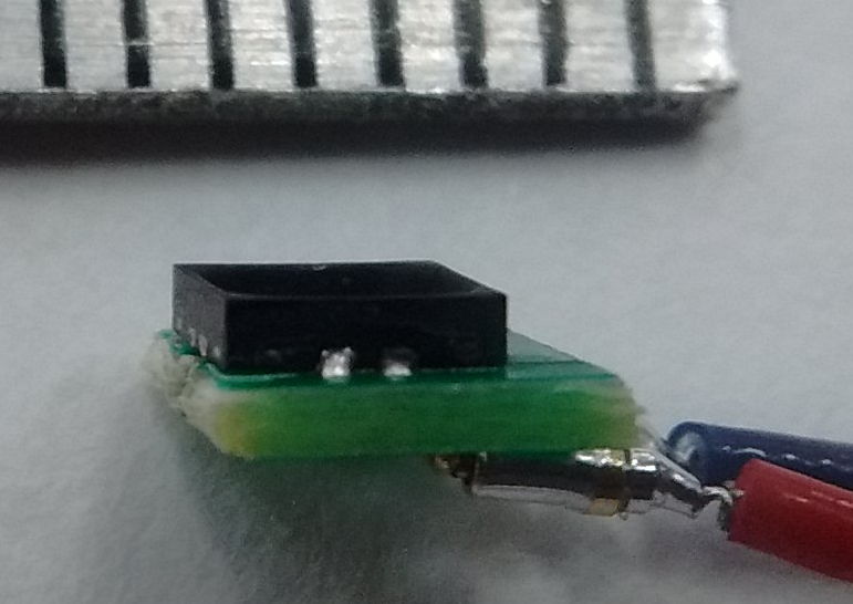
Figure: The Skull-Mounting LED. The LED die chip is wire-bonded into the 3 mm × 3 mm package, which is soldered on one side of a circuit board with two sockets that accept the stimulation lead pins.
When we connect the IST's 3.6-V stimulus voltage to an EZ500 LED through 25-Ω stimulus leads, approximately 30 mA will flow through the LED. The blue version will emit roughly 26 mW. The green version will emit roughly 12 mW. The EZ500 provides us with the most efficient conversion of battery capacity to light energy, and therefore offers us the longest operating life for a given stimulus regime.
| Property | Limit |
|---|
| Volume | 0.1 ml |
| Weight | 0.2 g |
| Optical Output Power | 26 mW Blue or 12 mW Green |
| Device Cost | $100 US QTY 10 |
Table: Target Specifications for the Skull-Mounting LED (SML).
The skull-mounting LED is designed to be used only once. Removing the LED from the dental cement fixture, and cleaning the contacts inside the sockets, will be hard, even after soaking for twenty-four hours in acetone. If we assume six implantations of each IST before it is no longer reliable, and one skull-mounting EZ500 per implantation, the the cost of IST components per implantation will be around $350.
Another option for the skull-mounting LED is to use the Luxeon Z LED from Philipps Lumileds. These LEDs are not as efficient as the EZ500, but they come in a variety of colors, of which the royal blue (445 nm), blue (465 nm), cyan (500 nm), green (525 nm), and deep red (650 nm) are efficient enough to support optogenetic stimulation of the first millimeter of brain tissue. Skull-mounting LEDs made with the Luxeon Z will be easier to manufacture. We could provide such LEDs for $50 a piece. Battery life for the same stimulus regime would be roughly half that of the EZ500 head fixtures.
Background
The IST development follows upon the development of the Implantable Sensor with Lamp (ISL) for rats. The cost of the A3030E development was shared by the Institute of Neurology (ION) at University College London, which paid $150k to OSI, and OSI itself, which contributed $20k. All hardware and software development was done at OSI, and all animal testing was done at ION. The ISL is now in final trials at ION. The proposed IST circuit is a simplified and smaller version of the A3030E. The skull-mounting LED is based upon the A3024HFD, but lacks the tapered fiber for delivery deeper into the brain.
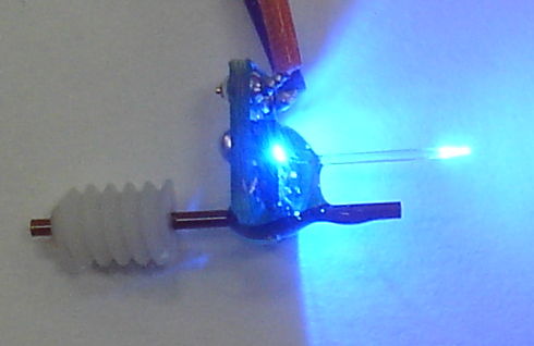
Figure: Rat-Sized Fiber-Coupled LED. A tapered 8-mm long fiber is glued to a 480-μm square LED. A guide cannula permits injections near the site of optical stimulation.
The A3030E has volume 4.5 ml once encapsulated with its 190-mAhr rechargeable battery and covered with three coats of silicone. Its single antenna serves to receive commands and transmit EEG samples, both of which take place in the 902-928 MHz ISM band. The A3030E logic chip is in a 100-pin TQFP package measuring 14 mm × 14 mm. The same logic chip is available in a 2.5 mm × 2.5 mm package, and it is this smaller package we propose to use in the mouse-sized IST.
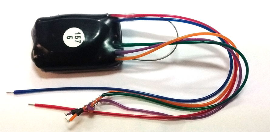
Figure: Rat-Sized Implantable Sensor With Lamp (A3030E). Note the green ground lead, spiral grounding spring, and black collars on the stimulus leads. These three features of the A3030E are designed to eliminate lamp artifact from its EEG signal.
The A3030E seeks to eliminate lamp artifact with a grounded spring wrapped around the stimulus leads and two collars on the leads that allow cement to hold the leads in place. These features complicate the surgery process. Any error in placing the grounding spring, and isolating the EEG leads from the stimulus leads, will result in lamp artifact corrupting the EEG signal.
Another way to eliminate lamp artifact is the separate the EEG monitor and the stimulator. We tried this with the Lamp-Only version of the ISL (A3030D-LO) and an A3038E rat-sized SCT. During several months of implantation of both devices in an adult rat, we saw no sign of lamp artifact in the EEG recorded by the SCT. The IST is designed to solve the lamp artifact problem by separating the stimulator from the monitor. We need no grounding spring, collars, or grounding wire. Surgery is as simple as possible.
Design Details
The IST provides three main functions when implanted. It carries out a stimulus sequence when it receives a command through its antenna. It acknowledges commands by transmitting an acknowledgement message through its antenna. It measures and reports its battery voltage with the same antenna. We expect reception of commands by the IST will be at least 90%, meaning no more than 10% of commands will be lost. Reception of acknowledgements from implanted devices in our telemetry systems is at least 90%. The probability of a stimulus command being received and executed while it's acknowledgement is lost will be less than 1%. So we might plan for 10% of stimulus command to fail and 1% to succeed without our knowledge. The same transponder antenna will also serve to report the IST's current battery voltage.
- Voltage-controlled radio-frequency oscillator to transmit messages in the 902-928 MHz band
- Crystal radio to receive commands
- Lithium-polymer battery to power the circuit and lamp
- Transistor switch to connect battery voltage to stimulus leads
- Programmable logic to decode commands, manage stimuli, and compose messages
- A circuit to measure battery voltage
The IST must be smaller than the ISL we designed for rats. In order to reduce the size, we move from a 14-mm square logic chip to a 2.5-mm square package containing exactly the same logic function. Instead of pumping 5.0 V for lamp power from the 3.6-V battery, we deliver power to the LED directly from 3.6 V through two short leads. The leads are only 45 mm in mice, compared to 150 mm in rats. Their resistance is lower, allowing us to drive the lamp current into the LED with only 3.6 V, while we needed 5.0 V in rats. This eliminates the boost converter and inductor of the A3030E. A few other package reductions and component eliminations combine to produce the following draft circuit diagram.
Figure: Schematic of Implantable Stimulator-Transponder. Compare to the ISL schematic S3030E.
The IST's 19 mA-hr lithium-polymer battery may be recharged through its lamp leads. The transistor switches Q2 provides a substrate diodes that allows us to apply a positive voltage to L+ and a negative voltage to L− in order to charge the battery.
Technical Challenges
Here are what we see as the greatest technical challenges we must overcome in the course of the IST development. The biggest challenges are those of miniaturization.
- Fitting all required parts onto a small enough circuit board to meet the 0.85-ml volume requirement.
- Sufficiently thin but adequately reliable epoxy and silicone encapsulation to meet the 0.85-ml volume requirement.
- Assuring corrosion resistance of smaller parts in humidity.
- Assuring reliability of circuit board with microvias required by the logic ship's 0.4-mm pitch ball grid array package.
- Accuracy of the battery voltage monitor that uses capacitor charge time.
The IST has no analog to digital converter (ADC). But the IST does need to be able to report its battery voltage. The voltage on a lithium-polymer battery allows us to deduce how much of its capacity remains. The IST will provide acknowledgement of command reception, and it will provide measurements of its battery voltage. Instead of using an ADC to measure the battery voltage, the IST will connect the battery voltage to a capacitor through a known resistor and measure how long it takes the battery voltage to charge the resistor to a certain threshold voltage. This time-based voltage measurement is new, and represents a minor technical challenge.
Budget and Schedule
The total cost of development of the Implantable Stimulator-Transponder (IST) is $24k US, to be paid by a collaborating institute. Any excess cost of development over and above this estimated $26k US will be paid for by Open Source Instruments out of its cash reserves.
- 80 hours circuit design engineering: US$8,000
- 80 hours technician labor: US$4,000
- Auxiliary IST hardware for collaborating group: US$3,000
- Prototype IST circuit assembly: US$4,000
- Final IST circuit assembly: US$5,000
The auxiliary hardware will consist of a 915-MHz Command Transmitter (A3029C), antennas, and other miscellaneous equipment needed to test and operate the ISTs. We propose to divide the development into three stages.
Stage One: The collaborating institute places an order for US$12k for three prototype IST circuits, eighteen prototype skull-mounting LEDs, and all necessary command transmission hardware to operate the devices while implanted. Delivery of these items will be twelve weeks after receipt of order.
Stage Two: The collaborating institute tests the prototypes over a twelve-week period, returning failed or exhausted devices to OSI for refurbishment as needed. The cost of refurbishing and recharging these prototypes is included in the development budget of Stage One. At the end of this testing period, the collaborating institute will return all three prototypes to OSI for final destructive corrosion analysis.
Stage Three: The collaborating institute places an order for US$12k for five final-version ISTs, and thirty skull-mounting LEDs of various types. Having received this purchase order, OSI modifies and corrects its prototype design as needed, and produces the final devices in twelve weeks. Included in this purchase will be fifteen refurbish and recharge services by OSI for any of these six ISTs returned by the collaborator to OSI. After the fifteen included refurbishment services are exhausted, additional refurbishment service can be purchased for US$200 each.
Following the completion of development, OSI expects to be able to offer the IST for $500 each in quantity 10, and the skull-mounting LED for $100 in quantity ten (the high-efficiency version) or $50 in quantity ten (the lower-efficiency version).
Conclusion
We propose a nine-month collaboration between Open Source Instruments Inc. (OSI) and a single collaborating institute to develop a fully-implantable optogenetic stimulator and skull-mounting LED for mice. The three months will produce a working Implantable Stimulator-Transponder (IST). Because we have already developed a rat-sized device that performs the same functions, we have only to miniaturize this existing design. We do not expect to encounter any major technical challenges in this development. The cost to the collaborating institutes will be limited to $24k. All additional and unexpected costs will be covered by the OSI.