[26-MAR-24] Depth electodes are used for implanting in animals in order to record potentials in the body while performing experiments. Since the electrodes are designed to be implanted they must be clean, durable, and straight.
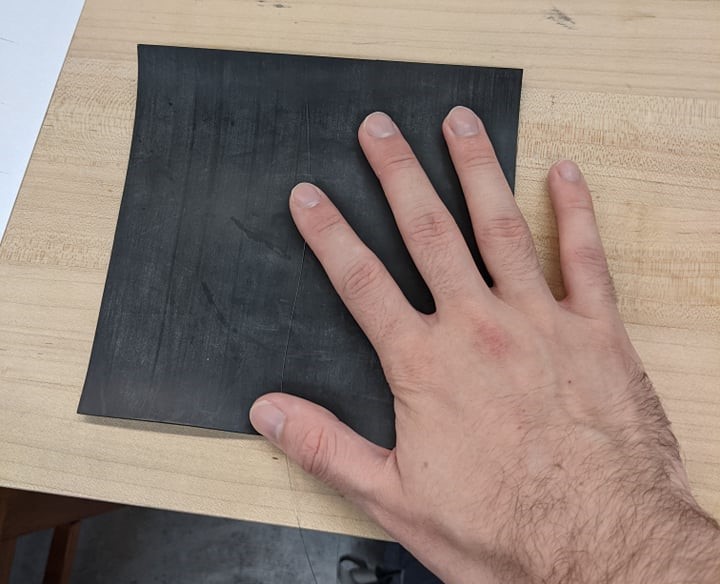
[26-MAR-24] To construct a depth electrode, you must begin by straightening stainless steel wire. In order to do this, we cut off a long strand of wire and place one end of the wire on a rubber sheet. It helps to tape the wire to the rubber sheet to ensure it won't slip our during straightening.
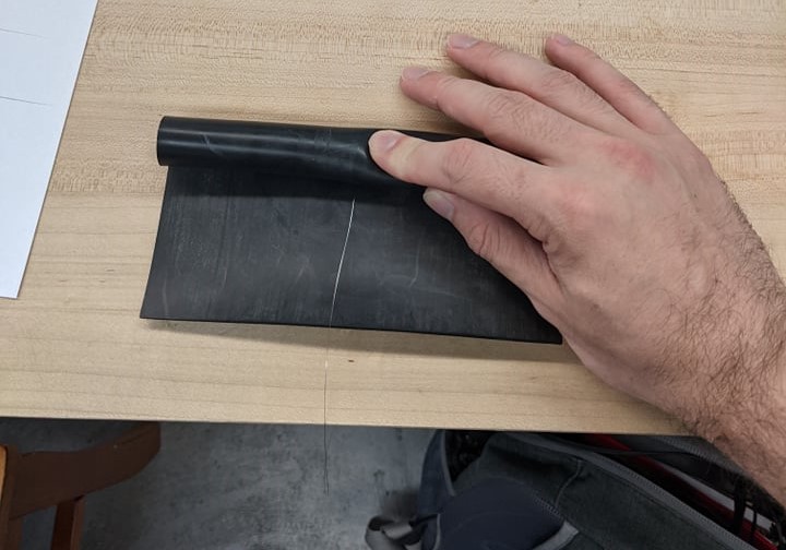
[26-MAR-24] Then, roll the wire into the rubber sheet and clamp down on the wire from outside the rubber sheet.
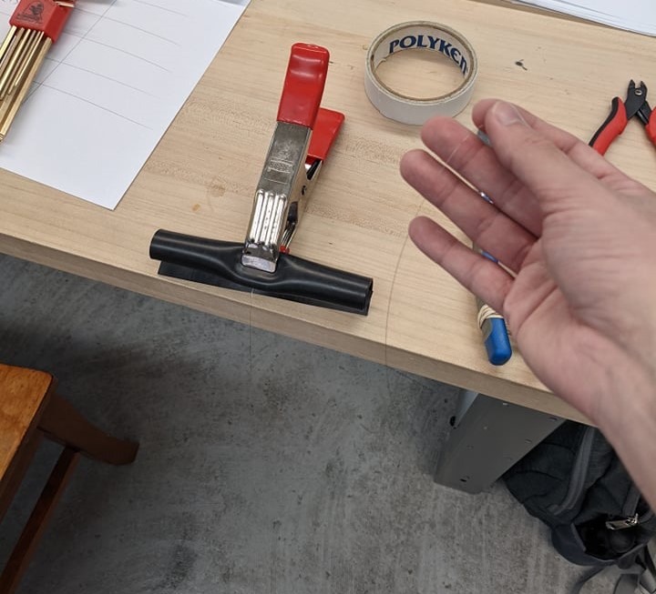
[26-MAR-24] Then, on the other end, we create a loop of tape so the adhesive is on the outside and wrap the end of the wire in it.
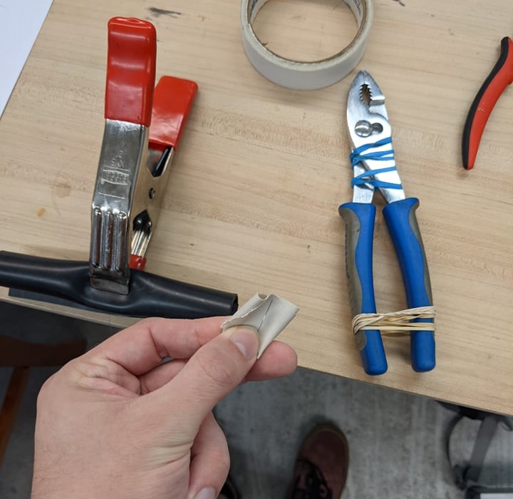
[26-MAR-24] Then take a pair of pliers with rubber bands around the handle and clamp it down around the tape. This ensures that at worst when the wire is being straightened it will slip out of the pliers rather than snapping. Additionally, we can place a weight of some sort on the other end of the clamp so that we don't have to hold the clamp as we're straightening the wire.
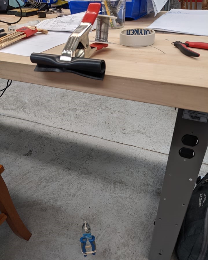
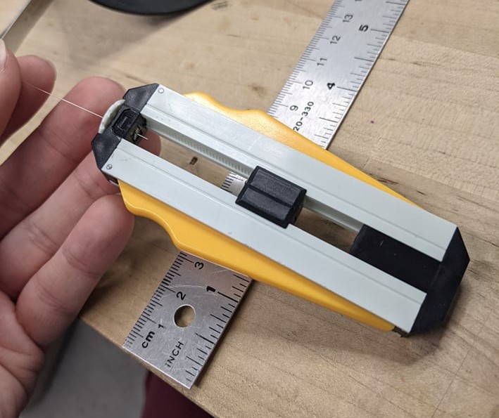
[26-MAR-24] Once this straightening apparatus is setup, we can begin straightening the wire. In order to eliminate the hysteresis of the wire we spin the pliers with rubber bands around it until the wire snaps where it meets the rubber mat. This will result in a stretch of wire with about 60% being perfect, straight, usable wire and the other portion being twisted and unusable.
[26-MAR-24] Once the wire is sufficiently straight, we can strip a small segment of the wire to allow for our socket to be soldered.
[26-MAR-24] During this stage only a small amount of wire needs to be stripped. There cannot be too much stripped wire underneath the socket.
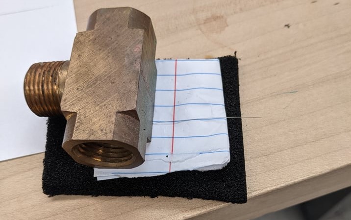
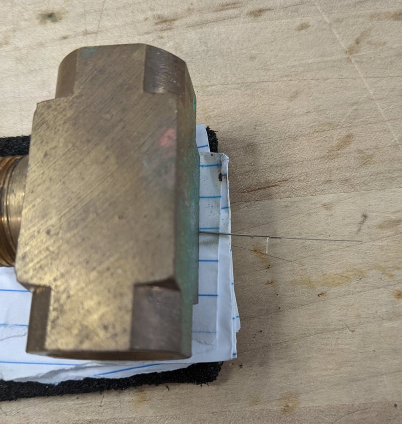
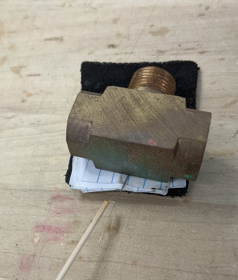
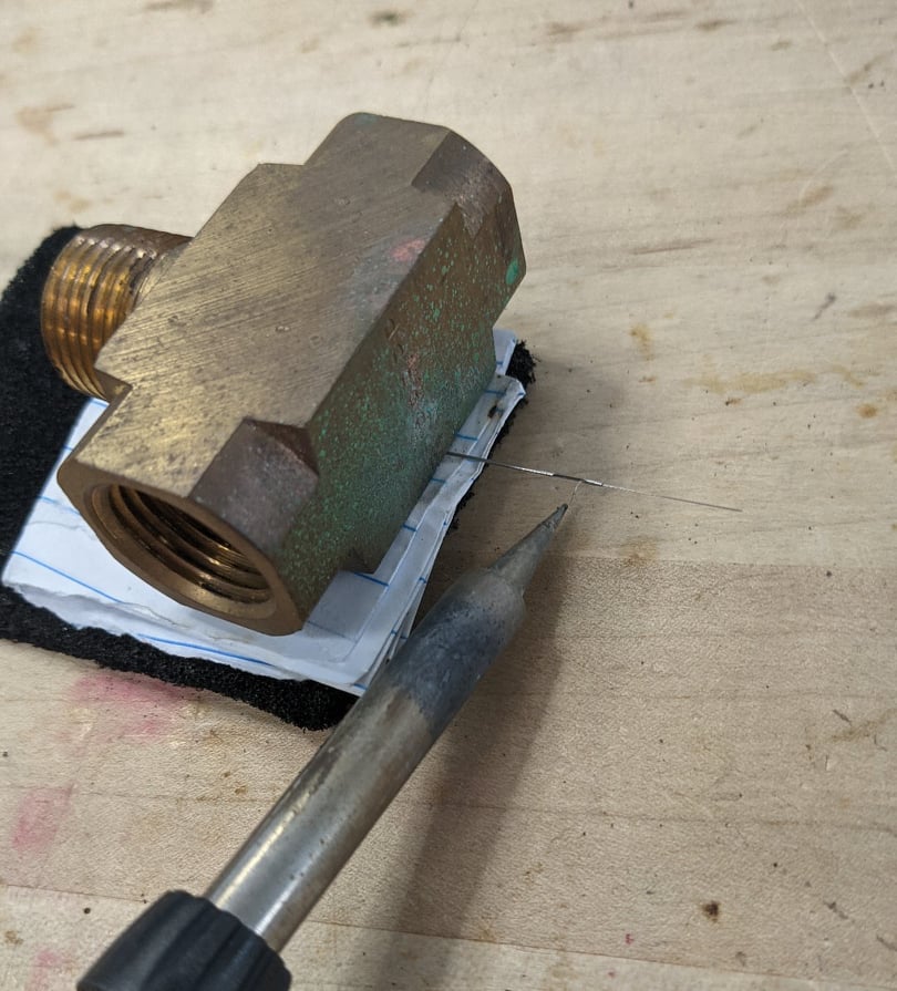
[26-MAR-24] We then weigh down the stripped wire so that it doesn't move while we try to solder it and it allows us to get the soldering iron underneath the wire.
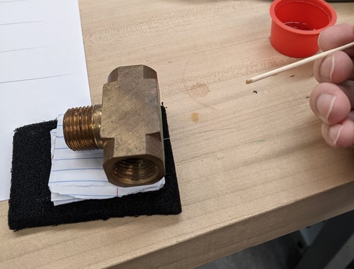
[26-MAR-24] We then tin the wire by applying acid flux to it with a wooden rod and heating it with the soldering iron. I reccomend placing the soldering iron underneath the wire and heating it, then coating the wire with acid flux. This will build up residue on the wire as well as making solder stick to it, so we must remember to wash each electrode once we've finished.
[26-MAR-24] If the wire was tinned properly, the socket should be held in place by the solder as soon as the iron stops heating the wire. During this step we need to ensure that no solder gets in the socket itself.
[26-MAR-24] The wire is then put through a guide cannula in order to hold the wire in place.
[26-MAR-24] We then make a loop atop the guide cannula and tape down the wire to the side of the guide cannula.
[26-MAR-24] Now that aluminum tape holds the wire in place, it only has some slight freedom to move up and down, just enough such that one can expose enough wire to make a cut near the socket if necessary.
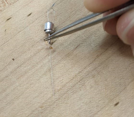
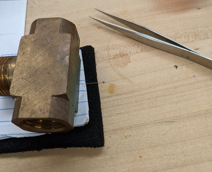
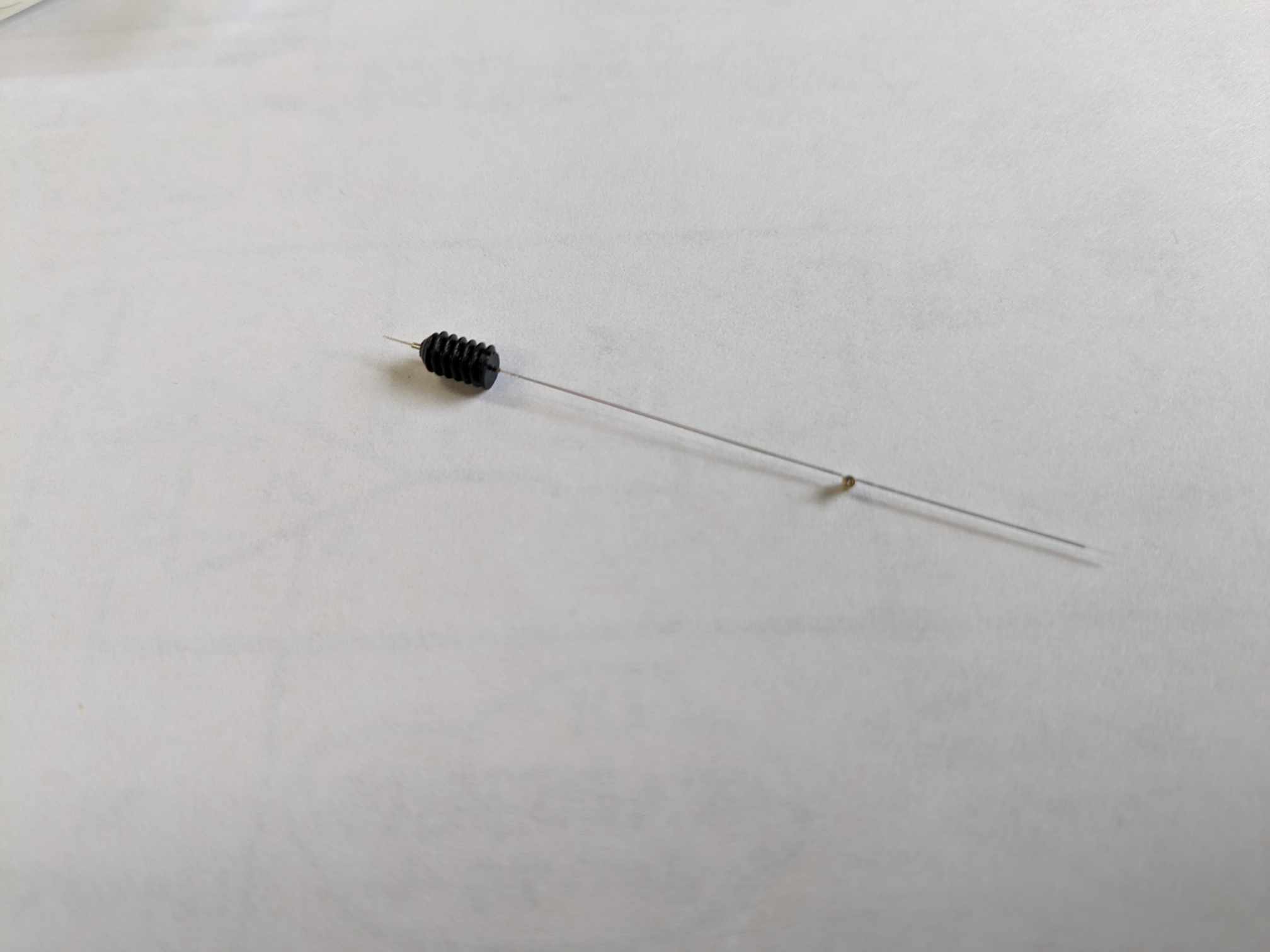
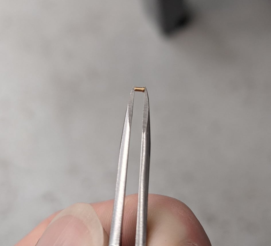
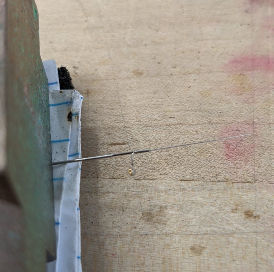
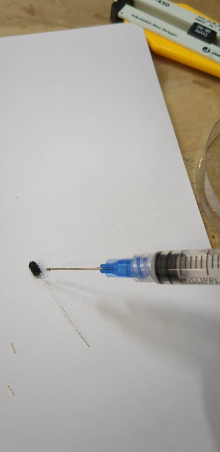
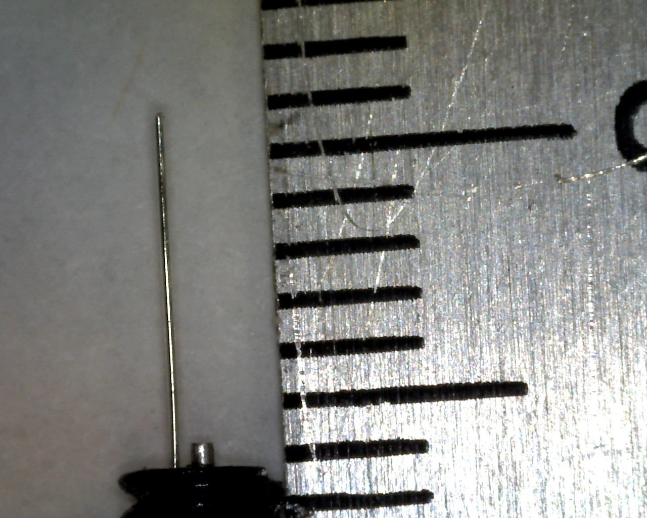
[26-MAR-24] Since this is being used for an implant, it is important that we remove the small sponge inside of the socket. We take a pin of a small enough diameter and push it through the socket to not only get the sponge out but to ensure there is no solder within the socket.
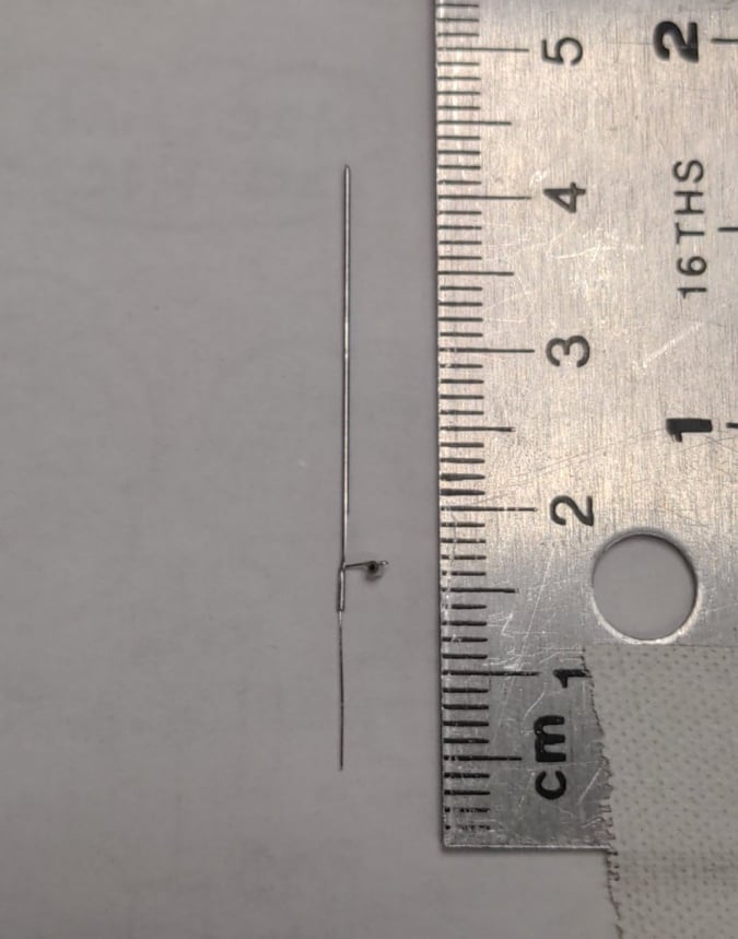
[26-MAR-24] If the pin goes all the way through, we must wash the electrode to make sure no residue is left on the wire. Once it is washed, the electrode is complete. We can also trim the lead of the electrode to a uniform length afterwards.
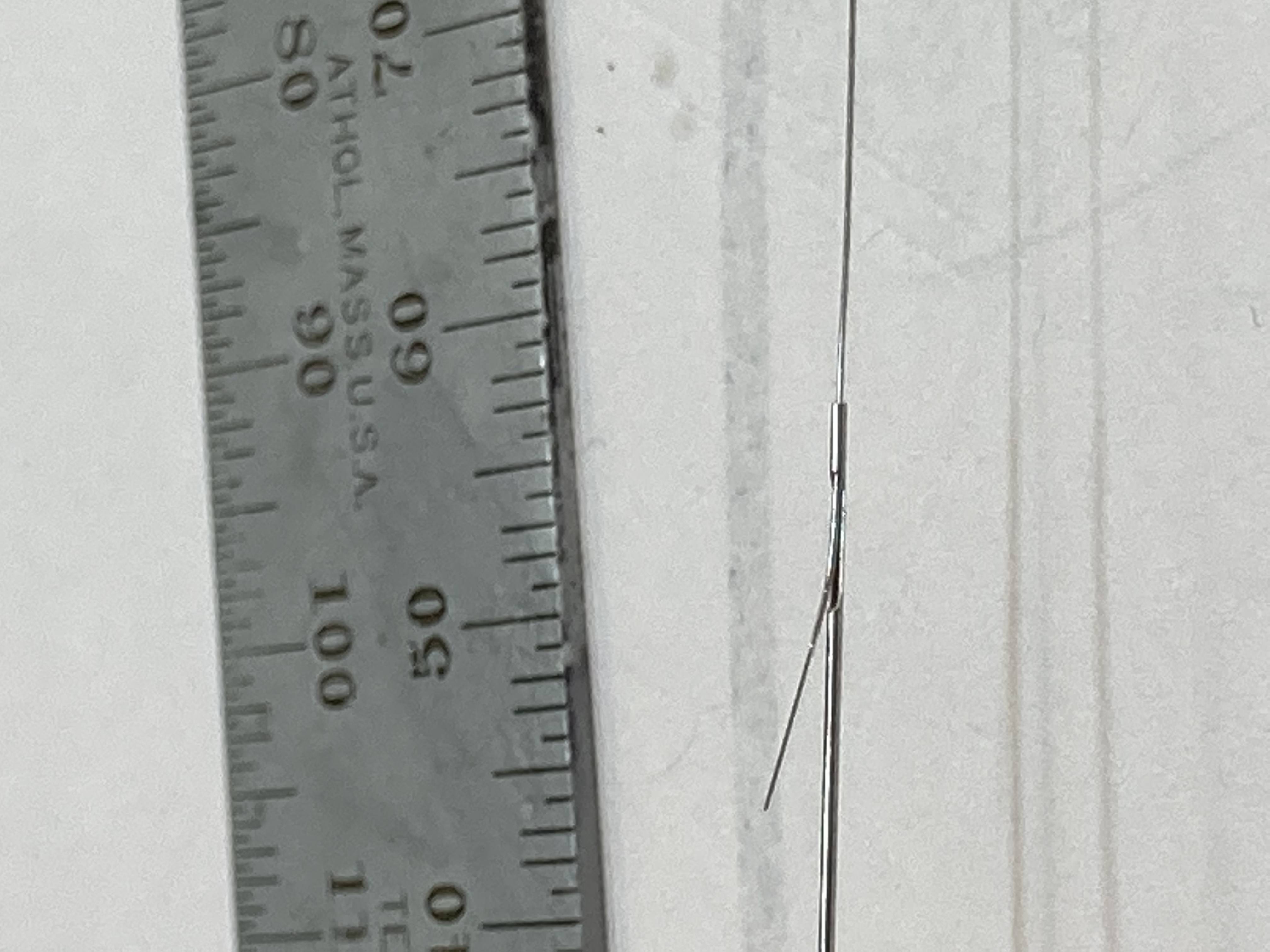
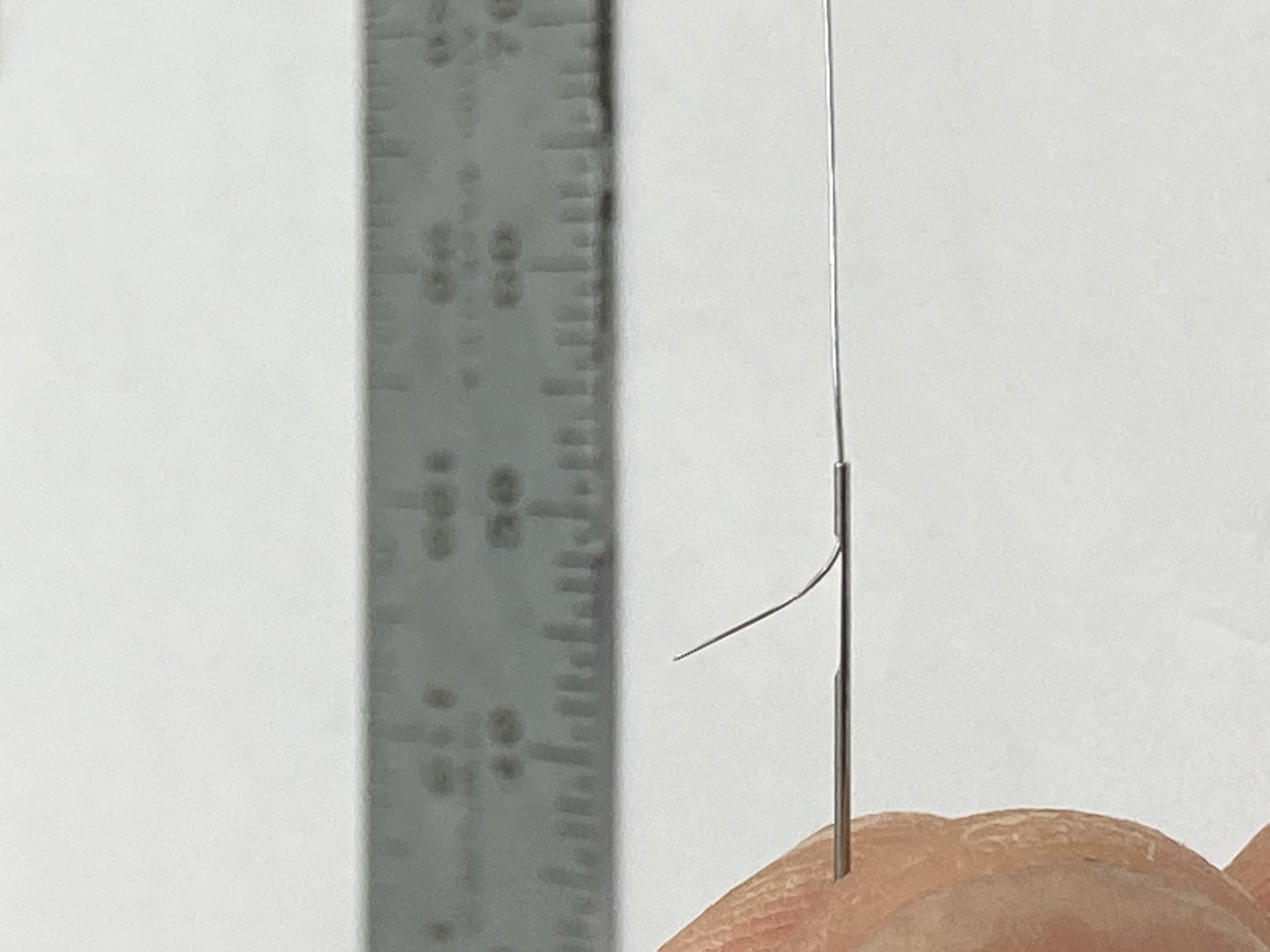
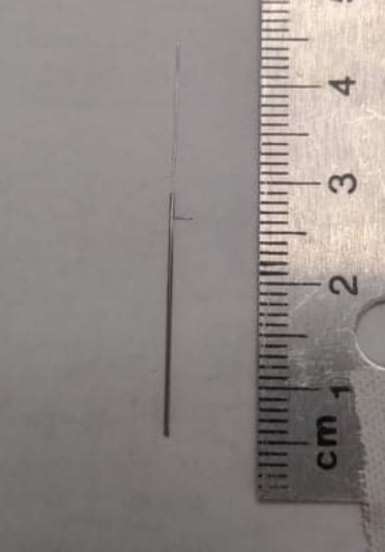
[26-MAR-24] The X-electrode requires the same technique of wire straightening used for the J-electrode as well as the same type of stainless steel wire. We begin by cutting off a 50-60mm segment of straightened wire and stripping one end by about 10mm. We can trim excess stripped segments later, in fact it is vital that any part of the wire that was squeezed using tweezers is cut off in the final electrode.
[26-MAR-24] Once the wire is stripped on one end, feed the stripped end into the top of the post (the hole closer to the cutout). The wire should poke out of the cutout on the post, allowing you to grab it and bend it.
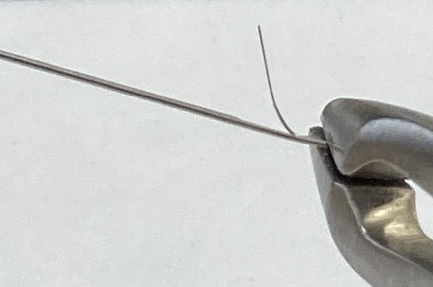
[26-MAR-24] Pull the wire out of the cutout until about 2mm of insulation is coming out of the post. Then, make a bend in the wire where it comes out of the post.
[26-MAR-24] Once the wire is bent and placed how you want it to be, we crimp the part of the post which the wire is going through. This ensures that the wire does not move during implantation.
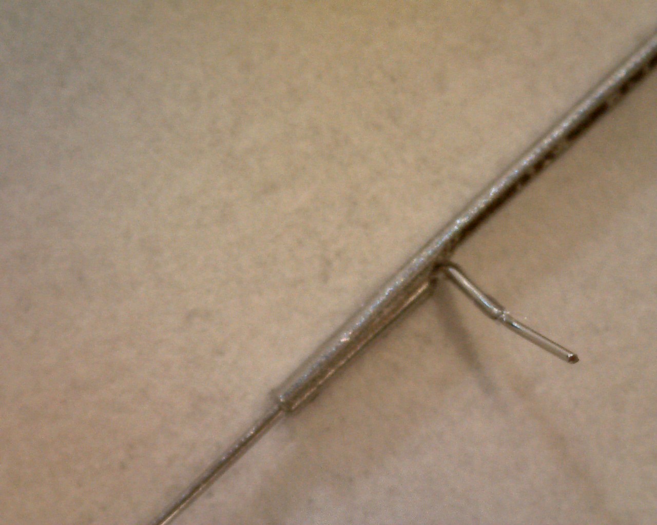
[26-MAR-24] If the wire cannot go through the post, I suggest stripping more wire on the end that is being inserted, then pulling the wire through with tweezers from the other side. This should leave more wire than necessary on the side that has been pulled through, so one can trim the wire sticking out to the desired length. Here are some images taken on a microscope of the crimped section up close.

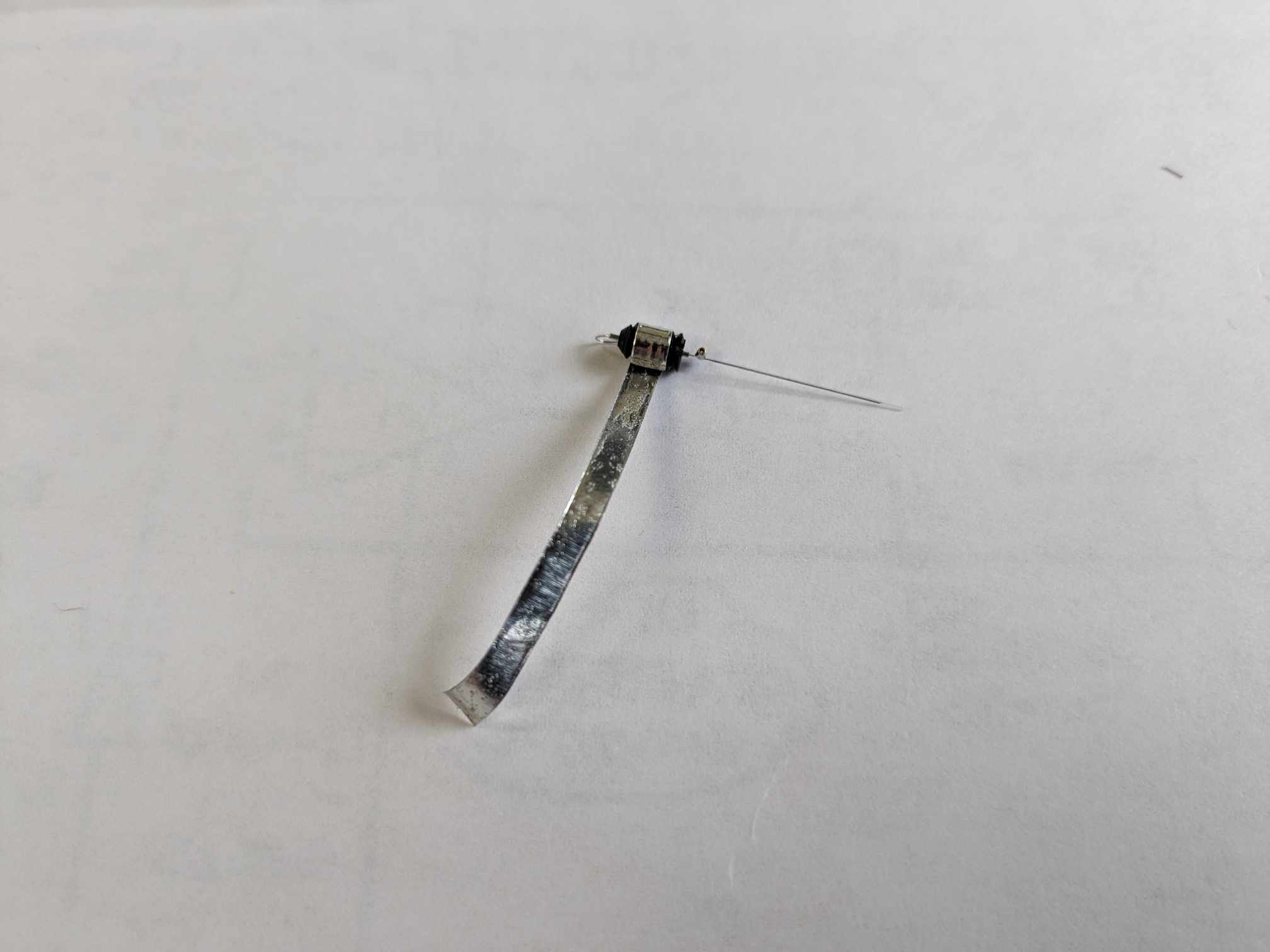
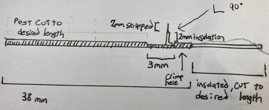
[26-MAR-24] After crimping, cut the post slightly and trim the parts of the wire that have been touched by tweezers and then the X-electrode is complete. To test the X-electrode, use the continuity function on a multimeter to ensure that the teflon was not damaged in the crimping. Simply touch the probes to the stripped part of the wire and the post to see if they are electrically connected. Below is a diagram of the X-electode with dimensions as well as an image of a finished X-electrode.
[26-MAR-24] To begin assembly of a W-electrode, we must complete all the same steps as the construction of an X-electrode. The difference between the X and W electrodes is that the W has a mill-max socket soldered onto the stripped part of the wire perpendicular to the post. To achieve this, we begin by tinning the stripped section of wire with acid flux. We must first weigh down the X-electrode to ensure it does not move while tinning.
[26-MAR-24] Once the electrode is secured in place, we use a wooden applicator to put acid flux on the stripped section of wire.
[26-MAR-24] Now, we apply heat with the soldering iron on the electrode to tin the wire, allowing us to solder to it.
[26-MAR-24] Next, we take a mill-max socket and solder it onto the part of the electrode that was just tinned. It is important that the socket is soldered close to the teflon as to leave as little stripped wire exposed as possible. This is so that less dental cement is needed when installing the electrode.
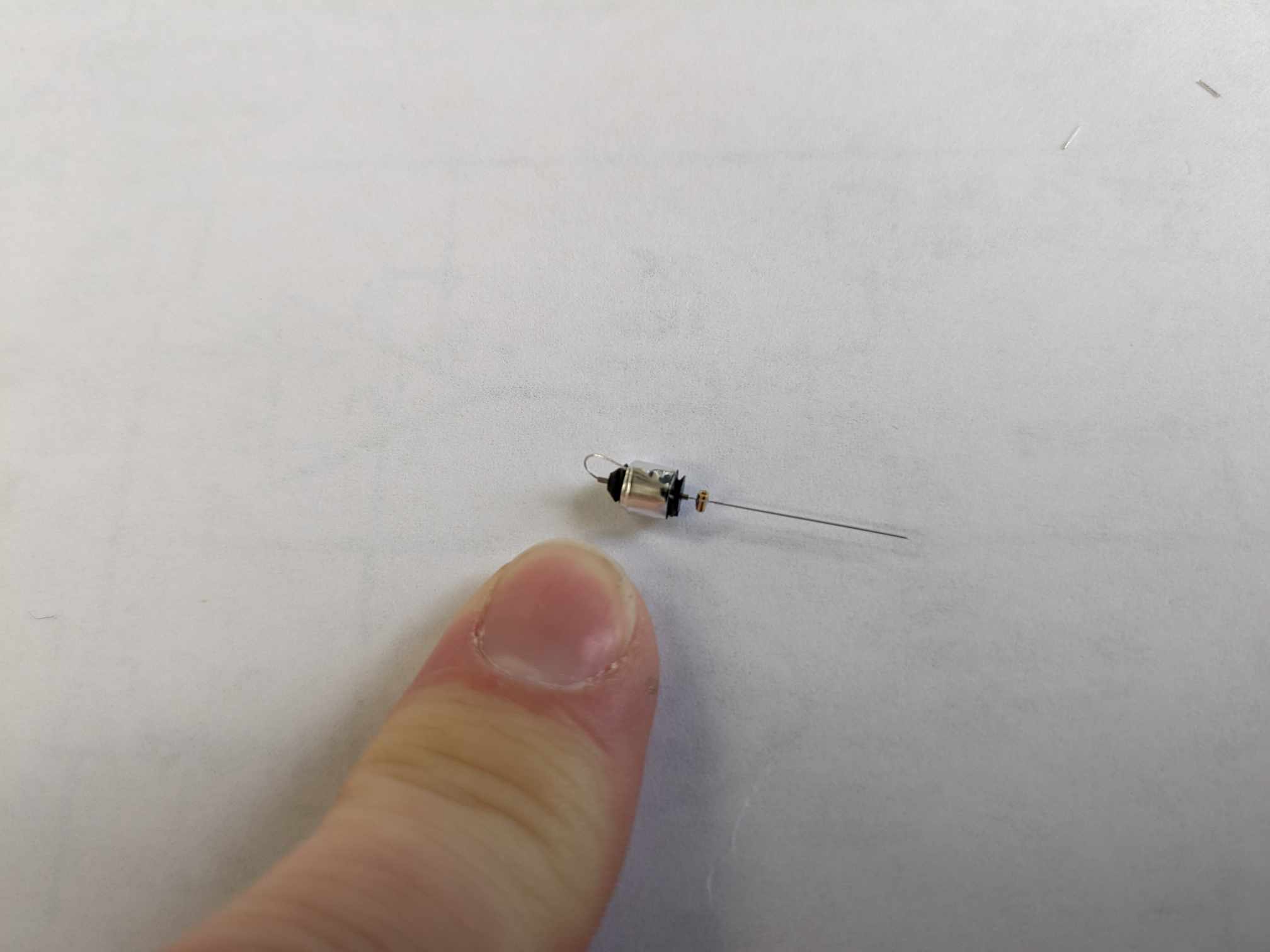
[26-MAR-24] Lastly, the electrode needs to be washed in order to clean off any residue left over by the acid flux. Similar to the J-electrode we should then use a mill-max pin to push through the socket of the electrode to make sure that no solder got inside the socket and is clogging it. If the pin passes through, the W-electrode is finished.
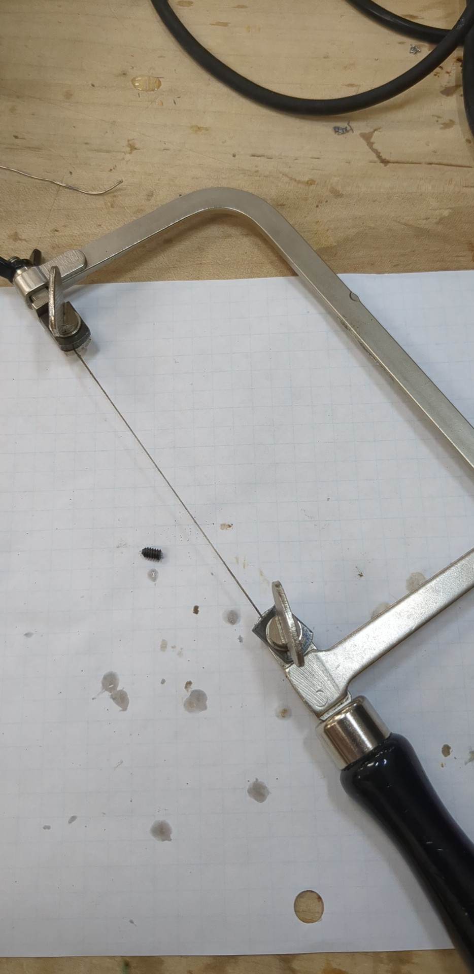
[26-MAR-24] To begin assembly of an R-electrode, we must first cut a slot in a guide cannula using a jeweler's saw.
[26-MAR-24] Once there is a cut in the cannula, we slide a wire (stripped on one end) into the slot and make a 90 degree bend in the wire.
[26-MAR-24] We then fill the slot with superglue and allow for it to cure.
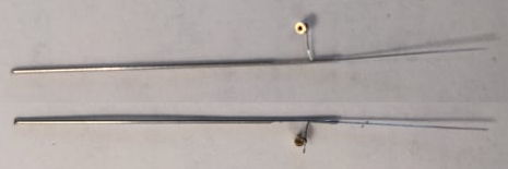
[26-MAR-24] After the glue has cured, we can solder a socket to the stripped end of the wire exactly how we would solder a socket to make a W-electrode. We tin the bare wire with acid flux, take a socket with tweezers in one hand and a soldering iron in the other in order to gently solder the socket to the tinned wire. Here are some images of finished R-electrodes with sockets soldered on.
[26-MAR-24] Some depth electrodes need to be modified specifically to meet the needs of our clients so there are a few different ways we can go about altering the electrode design to better fit its purpose. The W-electrode can be either right-handed or left-handed.
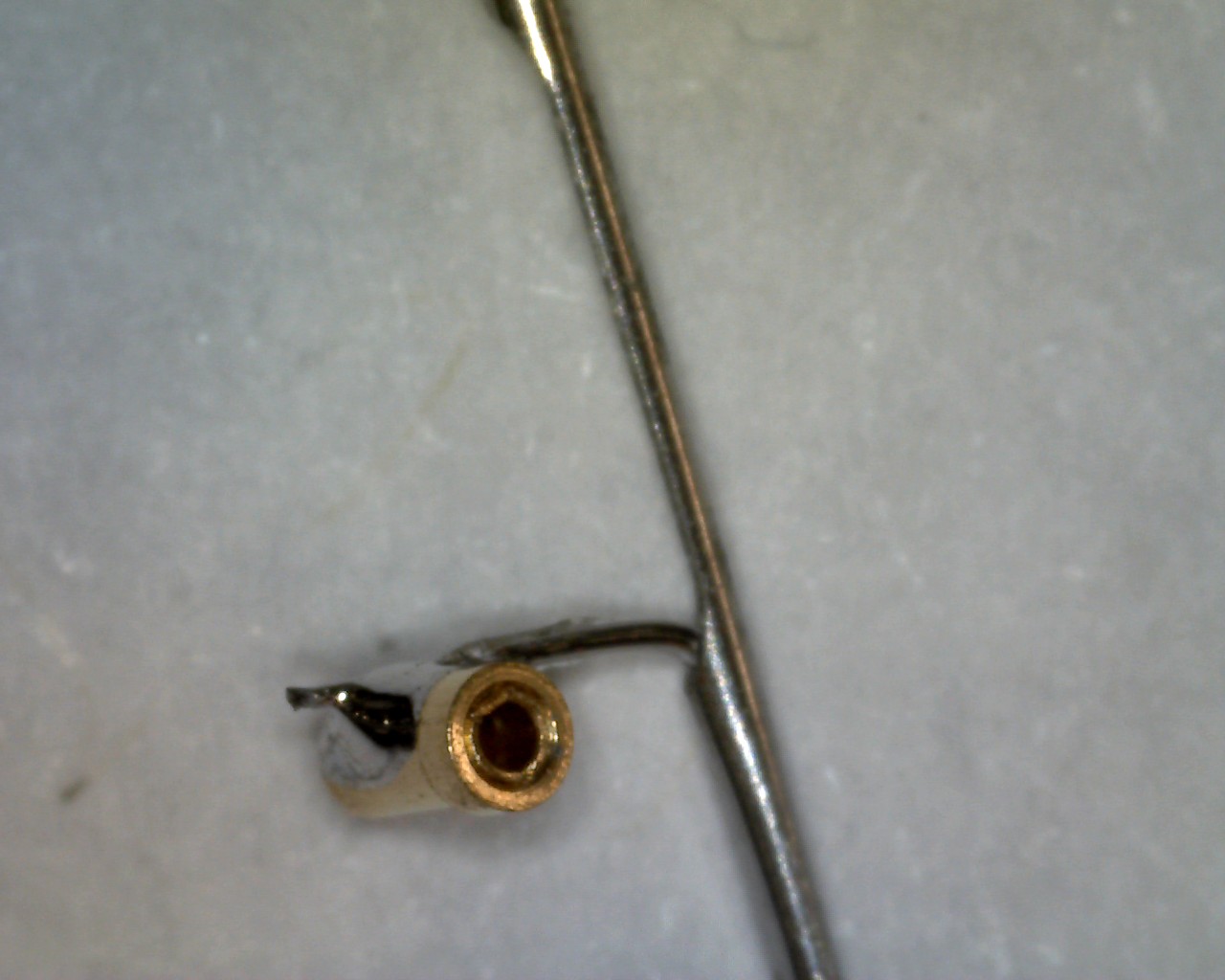
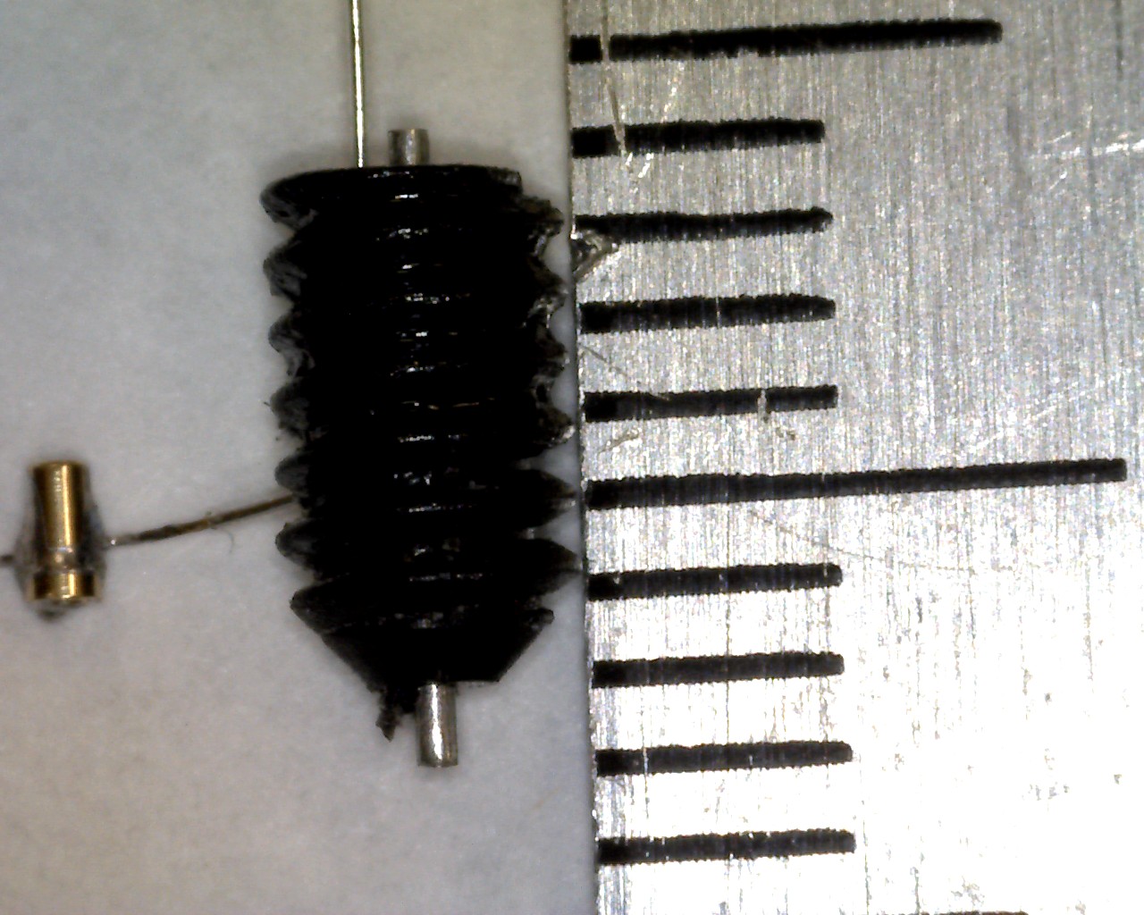
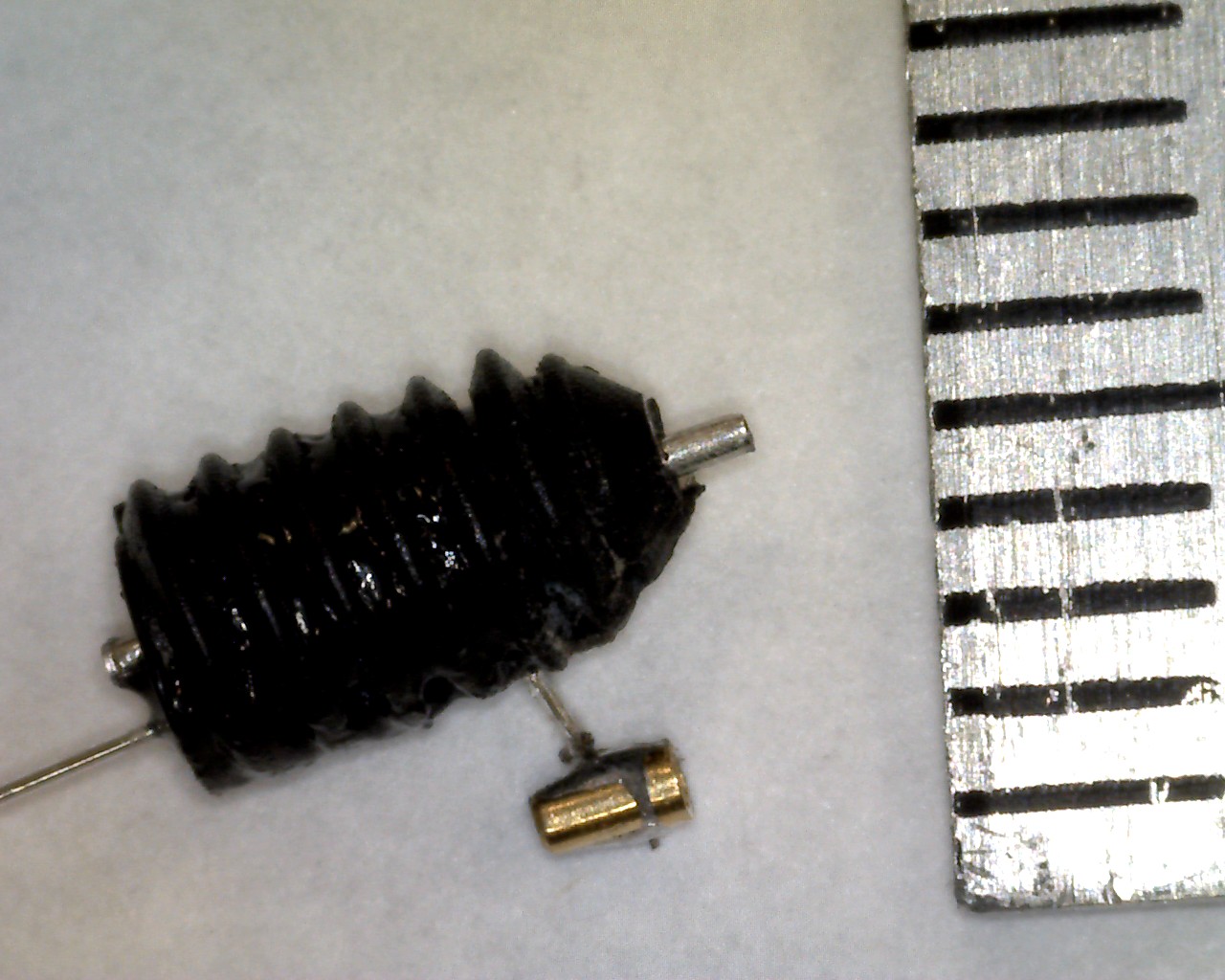
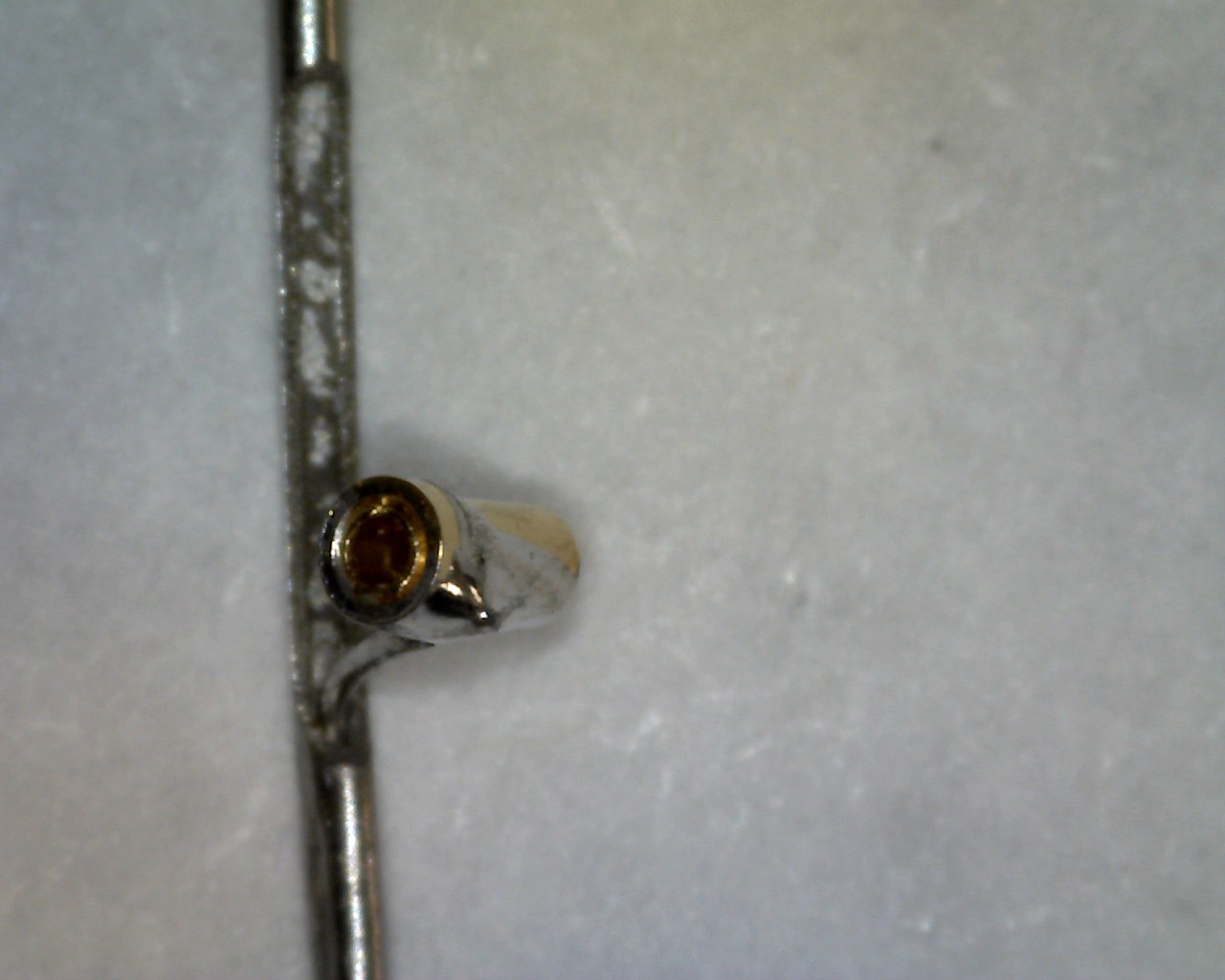
[26-MAR-24] The handedness of the electrode describes how the pin would be inserted (either on the right or on the left of the post). Here are some close-up shots of a right handed W-electrode.
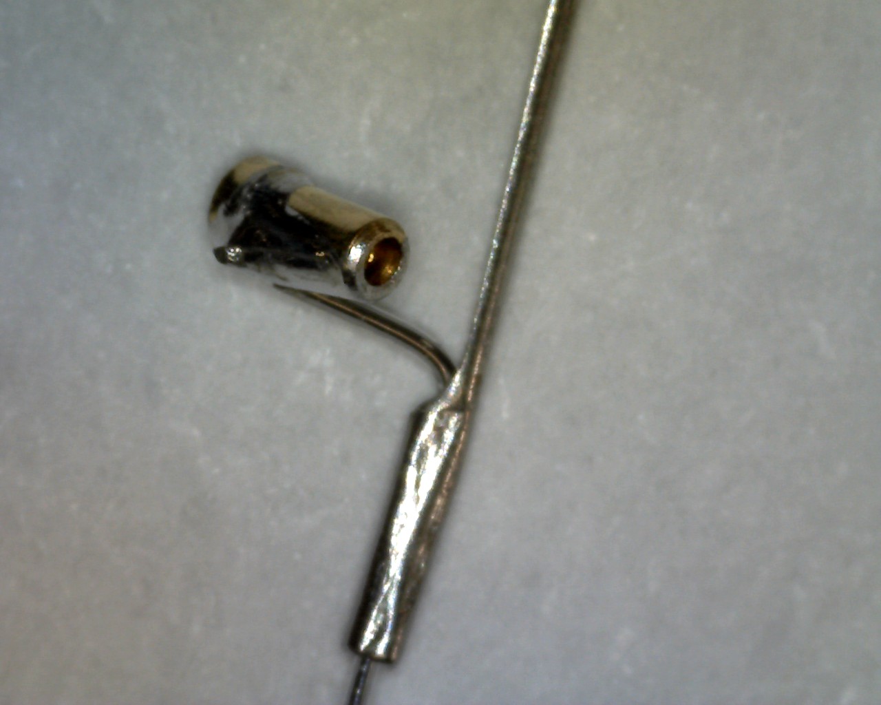
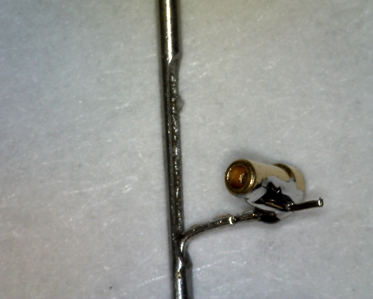
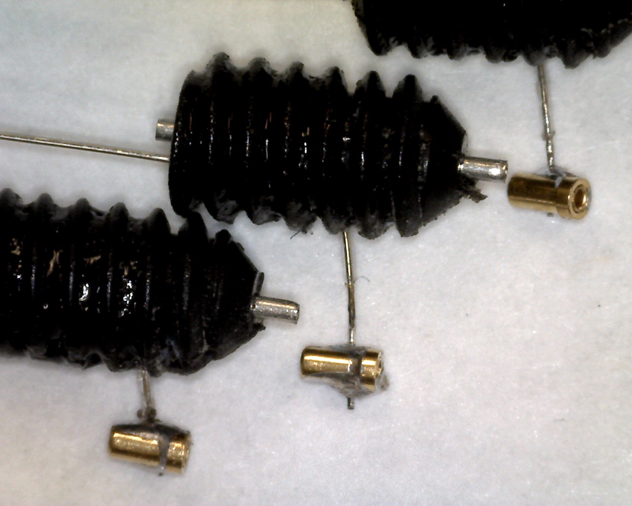
[26-MAR-24] Likewise, here are close-ups of the left-handed W-electrode.