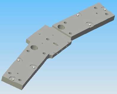
The subdetectors of the ALICE (A Large Ion Collider Experiment) detector at CERN will be held in place by a support structure that the ALICE collaboration calls their 'Space Frame'. Figure 1 shows the space frame. (The caption to Figure 1 defines the directions we refer to in this review: axial, radial, azimuthal, vertical, and horizontal. If you would like to see a montage of views of the space frame, click here.)

The ALICE collaboration will assemble the space frame above ground and survey its vertices with the help of retro-reflecting targets and traditional theodolites. The survey will tell them the locations of the vertices with respect to a single, frame-wide coordinate system. They believe that the survey accuracy will be sufficient to satisfy the demands of the detector so long as any further deformations can be predicted or measured with similar accuracy.
The space frame will deform under its expected loads. The space frame designers can predict the magnitude and primary directions of these deformations, but they cannot predict the deformations with sufficient accuracy to satisfy the demands of the detector. The ALICE collaboration has decided to use a monitoring system to measure the deformations of the space frame from an initial surveyed shape. After looking at the available monitoring instruments, Werner Riegler and Panos Christakoglou chose the BCAM (Boston CCD Angle Monitor), an instrument that combines cameras and light sources into a single enclosure that mounts on a kinematic ball triplet. Each BCAM comes with calibration constants that tell the user where its light sources are with respect to a coordinate system defined by its mounting balls, and also the locations of its camera apertures, the direction of each camera's axis, and all other parameters needed to make full use of the inherent precision of the camera and light source combination.
The BCAM measures the bearing (angular direction) of other BCAMs with respect to its mounting balls by taking digital photographs of of the light sources on the other BCAMs. By placing a pair of BCAMs, each looking in a different direction, on a single plate, we create an instrument that acts like a theodolite for light sources lying in the field of view of the two cameras. We can measure the angle subtended by any two such light sources at any point in the plate. We can measure the angle subtended to 70 µrad if we know the relative positions of the six mounting balls to an accuracy of 1 µm. We can measure changes in the angle subtended to 7 µrad if we know the relative positions of the six mounting balls to an accuracy of 100 µm.
In the sections below, we describe the use of 72 BCAMs to monitor deformations of the ALICE Space Frame, as proposed by Werner Riegler and Panos Christakoglou. We estimate the accuracy of this system, note the circumstances under which it will meet the demands of the ALICE particle detectors, and we consider how accurately the system will be able to deduce the geometry of the space frame without the help of surveying.
The ALICE Space Frame Monitoring System must determine the positions of a set of reference points on the space frame itself to an accuracy of better than 500 µm over the life of the detector. In this review we assume these reference points are precision holes drilled at the corners of the eighteen-sided outer rings at the ends of the space frame cylinder. There are eighteen such points at each end of the space frame, making thirty-six reference points in all. We will call them our vertices, and we refer to the points at one end of the cylinder as a set of vertices. According to this e-mail, we need to know the positions of the vertices with respect to the remaining vertices in the same set to 500 µm in all dirctions.
There are two ways in which the monitoring system may attain this accuracy. One is for the system to deduce the postions of the vertices from its own measurements alone, and another is for it to deduce only changes in the relative positions of the vertices, and add these changes to a survey of the initial positions of the same vertices. Both methods should be possible with the BCAM monitoring system proposed by the ALICE collaboration, but the survey will be necessary no matter what. Even if the monitoring system can deduce the absolute positions of the vertices, a survey would be necessary to confirm the system's performance.
When we consider monitoring deformations alone, ALICE tells us that these deformations will take place in the radial and azimuthal directions, but not in the axial direction (see Figure 1 for definitions of these directions). We expect movements of up to 5 mm in the radial and azimuthal directions, but only 100 µm in the axial direction. Because the axial deformations are so small, there is no need for the monitoring system to measure them. Because the deformations are taking place in only one direction, the monitoring system can simply measure the size of local deformations, and assume that the entire deformation takes place in a plane perpendicular to the space frame axis.
Another constraint upon the space frame deformations is that the separation of neigboring vertices will change by less than 100 µm, because the beams between the vertices are stiff and short. The may rotate with respect to one another around a vertex, but they will not compress, expand, or bend significantly. Consequently, we can assume, when measuring the position of vertices to 500 µm accuracy, that the beams between the vertices are stiff.
The system proposed by ALICE, after consultation with Open Source Instruments Inc, consists of two BCAMs mounted on a single plate at each vertex. The mounting plate (see Figure 2) carries two sets of three balls to hold the two BCAMs, and a precision pin and slot to center and orient the plate with respect to the pin or hole that defines the vertex position. These mounting plates will be machined to 100-µm precision and the mounting balls will be glued in place to 10-µm precision.
There will be one such plate at each of the eighteen vertices at each end of the space frame, making thirty-six plates in all, and seventy-two BCAMs. The arms of the plate, each of which holds a BCAM, fit into the channels between the ribs of the beams that meet at the vertex. Figure 3 shows one end of the space frame. The vertices of the monitoring system are at the corners of the outer ring of support beams.

One of the BCAMs on each plate will be a Blue Azimuthal BCAM and the other will be a Black Azimuthal BCAM. These two are mirror images of one another, and face one another perfectly when lined up in, for example, a U-channel barely wider than the BCAM chassis, which is exactly the arrangement in the space frame monitoring system. The BCAM on the left of each mounting plate might be blue, and the one on the right black, so that each BCAM looks at one of the opposite color. With nominal BCAMs in their nominal positions, the lens of the black BCAM will be at the center of the field of view of the blue BCAM. The lasers of the black BCAM will be half-way up the field of view of the blue BCAM, and either side of the center. The BCAM image will look something like Figure 4. Each BCAM provides two light sources, and there is one BCAM looking at each light source, so we will obtain images of 72 light sources for each set of eighteen vertices.
Each plate will measure the bearing of the light sources on its two neighboring plates with respect to the vertex upon which it mounts. These measurements will allow the BCAMs on each plate to measure the angle subtended at the local vertex by the two neighboring vertices. The monitoring system operates by measuring all eighteen internal angles of the eighteen-sided outer ring. Because we can assume the connections between the vertices are stiff, these eighteen angles are more than enough to allow us to measure deformations of the structure.
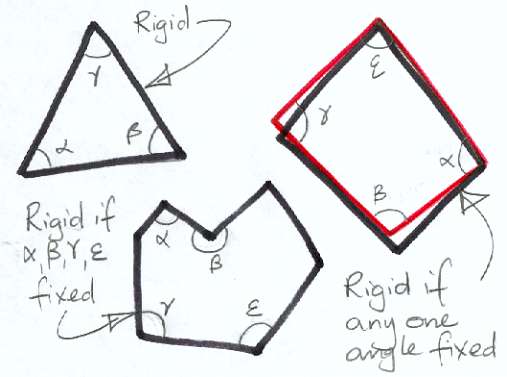
Figure 5 attempts to show how the shape of a polygon with stiff links between its vertices is fixed so long as no more than three of its internal angles are free to change. If, instead of "free to change" we think of "unknown", then we can see that the shape of a polygon with stiff links of known length is known so long as no more than three of its internal angles are unknown. If we know the initial positions of the vertices of our eighteen-sided space frame polygon, then we will be able to measure their movements by measuring fifteen or more of the polygon's internal angles. If we measure more than fifteen angles, our measurements contain redundant information, which we can exploit with the help of a geometric fitting program like ARAMYS. We will assume from now on that such a program is in place, and we will not concern ourselves with the details of its implementation.
As you can see from Figure 3, the separation of neighboring vertices in the eighteen-sided ring of the space frame is roughly 1.3 m. The range of the BCAM sources from the viewing BCAM lenses will be roughly 90 cm. The useful field of view of a BCAM is 40 mrad in the direction parallel to its mounting plate, and 30 mrad in the direction at right angles to its mounting plate. The field of view of each BCAM will cover a 36 mm by 27 mm rectangle with its nominal center on the lens of the BCAM it views. The point sources on either side of a BCAM lens are separated by 16 mm, so they can move by 8 mm in any direction, and still remain in the field of view.
The monitoring system is supposed to operate with deformations of up to 5 mm, which we assume means that one vertex can move by up to 5 mm with respect to another. The system proposed by ALICE allows for up to 8 mm of movement.
Figure 6 shows three neighboring plates in the Space Frame Monitoring System. Black and blue BCAMs watch one another allong 900 mm of a 1300-mm beam. The BCAM cameras look directly up and down the beam. In the drawing, the three neighboring vertices are named A, B, and C. If A moves a distance y in a direction perpendicular to the axis of the blue BCAM camera at vertex B, then this blue BCAM sees the bearing of the sources on the black BCAM at vertex A change by y divided by the separation of the BCAMs, which is 900 mm.

The BCAM measures changes in the bearing of light sources within its field of view with precision 5 µrad. The BCAMs at each vertex will monitor changes in the bearing of light sources on neighboring BCAMs with precision 5 µrad, which is equivalent to a movement of 900 mm x 5 µrad = 5 µm. When it comes to monitoring the movement of one vertex with respect to another, we see that the geometry of our monitoring system is complicated by the fact that the camera lenses are not exactly at the vertices, and nor are the light sources. Let us assume, however, in order to obtain an estimate of the precision of the BCAM monitoring system, that all the lenses and light sources of each BCAM plate coexist at its vertex. With this assumption, the BCAMs at vertex B measure the angle ABC directly. In the actual system, they measure the same angle, but do so indirectly. Even though the measurement is indirect in the actual system, it is nevertheless just as accurate, or marginally more accurate, because the BCAMs are closer than 1.3 m, and mounted upon stiff plates.
Let us proceed with our assumption that lenses and light sources coexist at each vertex. With this assumption, if we want to measure the movement of vertex C in Figure 6 with respect to vertex A, we must add two BCAM bearing measurements to get the change in angle ABC. Our precision in measuring ABC is 7 µrad, so our precision in measuring the movement of C with respect to A becomes 7 µrad x BC = 10 µm, because BC is 1.3 m. The reason that the length of AB does not come into the calculation is that we assume the axis of the coordinate system in which we measure the movement of C is parallel to AC, with its origin at A.
If we want to measure the movement of a vertex F relative to A, we must pass through four vertices B through E, as shown in Figure 7. From our initial survey, we know the lengths BF, CF, DF, and EF, and because each of them represents a stiff beam on the outer edge of a polygon, we assume each is constant. As the polygon distorts we measure changes in its internal angles with precision 7 µrad. Figure 7 shows a coordinate system with origin A and x-axis AB. We use our measurements of the internal angles of the polygon and our knowledge of the lengths of its sides to deduce the movement of F with respect to A in this coordinate system.
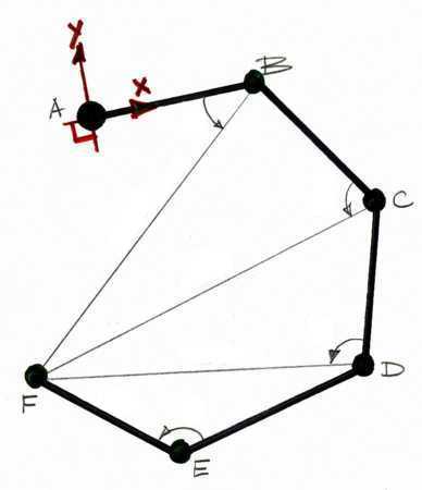
If you study Figure 7, you will see that if ABC alone changes by a small angle b, ABF changes by the same amount, and F moves by bBF. If angles BCD, CDE, and DEF alone change by c, d, and e respectively, then F moves by cCF, dDF, and eEF. Let us assume that each of the sides of our polygon are the same length, l. This assumption is true for ALICE, in which l = 1.3 m. Let us also assume that all six vertices lie along a straight line, instead of curving around in a polygon. This assumption is not true for ALICE, but we will correct for this discrepency later. With these two assumptions, we see that our error in measuring the movement of F due to our error in measuring ABC is 7 µrad x 4l, and from the measurement of BCD is 7 µrad x 3l, and so on. The errors in our measurement of the position of F lie along our y-axis, and we can add them in quadrature, giving us an error of 7 µrad x sqrt(30) x l = 50 µm.
In ALICE's eighteen-sided polygon, we have a vertex J opposite A with eight vertices in between. If all ten vertices lay along a straight line, our error in measuring the movements of J with respect to A would be 7 µrad x sqrt(204) x l = 130 µm. But the ten vertices do not lie along a straight line. Instead, they bend around in a half-circle, so our actual error in monitoring J will be smaller, approximately in proportion to the ratio of the diameter of a circle to half its circumference. Consequently, we expect our error to be closer to 100 µm than 130 µm.
The monitoring of one vertex with respect to the vertex opposite on the polygon is the least accurate of all our measurements. On average, the separation of two vertices is only four meters, compared to the eight meters between A and J (see end view). If we pick any two vertices at random, the precision with which the BCAM system can monitor the position of one with respect to the other will be roughly 50 µm.
Another way to arrive at our estimate of 50 µm precision from our worste-case precision of 100 µm is to consider transforming all movements we measure at A into another coordinate system at the geometric center of all the vertices. In this case, an error of 100-µm measuring the position of J with respect to A becomes a 50-µm error measuring the position of A in the new coordinate system, combined with a 50-µm error measuring the position of J.
As we showed in Figure 5, we need only fifteen internal angles to reconstruct the shape of our eighteen-sided polygon. We can use our measurement of three extra angles to make a slight improvement in the precision of the system, but not a significant improvement.
The precision of the BCAM system is one thing, and its absolute accuracy is another. The system proposed by ALICE does not use the BCAMs for the initial measurement of the positions of the vertices. In his proposal, the measurement begins with a survey to establish the positions of the vertices, and then uses the BCAMs to measure changes in these positions. The accuracy of CERN's surveys on structures eight meters across is, from our experience at the ATLAS H8 Test Stand, roughly 300 µm, which is much larger than the precision of the BCAM system. The accuracy of the system proposed by ALICE is therefore dominated by the accuracy of the initial survey.
We now consider how well the monitoring system can measure the relative positions of the vertices immediately after it is installed, without any help from a survey. Let us suppose that we do the following in preparation for an absolute measurement of the vertex geometry.
With these conditions met, the BCAM plate at vertex B in Figure 6 will be able to measure the absolute value of angle ABC. The CMM precision and BCAM calibration precision combine to give us an accuracy of better than 70 µrad when measuring this internal angle. In other words, the absolute accuracy of such a system, when we turn it on, will be 70 µrad compared to its precision of 7 µrad. Our absolute accuracy in measuring the position of vertex J with respect to vertex A will be ten times greater than our precision, and the overall rms error in measuring the absolute position of one vertex with respect to another roughly 500 µm.
The BCAMs Open Source Instruments Inc. will supply to ALICE will be fully calibrated BCAMs, irrespective of the use to which the BCAMs will be put. Measuring the CBAM plates, one the measurement program has been written for a CMM, will not cost more than $100 per plate. All the software and databases needed to implement the absolute measurement directly with BCAMs will already be in place simply to provide the proposed relative calibration. We conclude that the additional cost of implementing an absolute measurement to 500-µm accuracy with BCAMs alone is less than $4000 for the entire Space Frame Monitoring System.
The final measurement we consider is the BCAM's range measurement, which we obtain from measuring the angle subtended by the two light sources. Consider the blue BCAM at vertex B in Figure 6. This BCAM sees both light sources on the black BCAM of vertex A. From our calibration of the black BCAM, we know the separation of these two light sources to about 5 µm. We know the location of the blue BCAM's pivot point (the point through which all straight light rays pass on their way from a light source to the image sensor), to about 300 µm, and we know the separation of the pivot point and the image sensor surface to about 30 µm. When we measure the separation of the images of these two light sources on the image sensor, we can, by similar triangles, deduce the range of the light sources from the pivot point, and so we can determine the length of AB to about 500 µm absolute, and track changes in this distance with 50 µm precision.
| Measurement | Error (Measured Plates) | Error (Unmeasured Plates) |
| Radial Movement of Neighboring Vertices | 10 µm | 10 µm |
| Radial Position of Neighboring Vertices | 100 µm | 1000 µm |
| Radial Movement of Opposite Vertices | 100 µm | 100 µm |
| Radial Position of Opposite Vertices | 1000 µm | 10000 µm |
| Movement of Vertex in Central Coordinates | 50 µm | 50 µm |
| Position of Vertex in Central Coordinates | 500 µm | 5000 µm |
| Azimuthal Movement of Neighboring Vertices | 100 µm | 100 µm |
| Azimuthal Position of Neighboring Vertices | 500 µm | 500 µm |
Table 1 summarizes the precision and accuracy of the system with and without measurement of the BCAM mounting plates. When the plates are not measured, we assume the positions of the mounting balls are known to the machining precision, which is about 100 µm.
Our measurement of the eighteen vertices around each eighteen-sided ring will succeed so long as we are able to measure at least fifteen of its eighteen internal angles. Let us suppose that one BCAM camera (but not its sources) on one plate fails at random. We will lose our measurement of one internal angle. This can happen in three places, and the monitoring system will remain operational. Table 1 shows how many internal angle measurements we lose for various device failures. Note that we do not specify whether the lost internal angle measurements are next to one another or separate, because it makes no difference. Only the total number of angles is important. We can lose no more than three angle measurements no matter which angles they are.
| Failure | Loss |
| One Camera | 1 |
| One Source | 0 |
| Two Sources on Same BCAM | 1 |
| One BCAM | 2 |
| Both BCAMs on the Same Plate | 3 |
| Two BCAMs Facing One Another | 2 |
| One BCAM Cable | 2 |
| One U-Channel Line of View Blocked | 2 |
A brief look at Table 2 shows that we cannot tolerate the failure of two BCAM at random around the polygon, nor the blocking of more than one line of sight down two U-channels at random. When we say "at random" we mean "don't assume they are neighbors because if you do their effects will overlap and be less severe when added together".
In theory, it is possible for a BCAM to fail in such a catastrophic way that it brings down the data acquisition power supplies. If this happens, we must replace the BCAM, or unplug it from its multiplexer, or unplug the multiplexer from its driver (see below for a description of the data acquisition architecture). If we cannot get to the multiplexer or the BCAM, our only option is to unplug the multiplexer from the driver, which will disable as many as nine additional BCAMs. Knowing the dire consequences of such a failure, we designed the BCAM electronics to guarantee that the BCAM, if powered off, powered on again, and left alone, will not bring down the data acquisitions power supplies under any circumstances. By turning off the data acquisition power for a few seconds, and removing the failed BCAM from the data acquisition cycle, we guarantee that its failure will not affect any other devices in the system. Our design has proved itself effective in this respect, and we are confident that the probability of such catastrophic power-draining failure is negligible. We assume, therefore, that BCAM failures will be independent.
It remains for us to calculate the mean time between BCAM failures in a set of eighteen BCAMs. At the H8 test stand at CERN, forty BCAMs with the latest electronics (Polar BCAM Head) have been running for six months with no proven failures. We have never had a BCAM with the new electronics fail in our laboratory after initial testing and calibration. The BCAMs used in the space frame monitoring system contain rugged electronics (Azimuthal BCAM Head). They will be mounted and used for at least a month before they are lowered into the ALICE detector hall. We are confident that fewer than 10% of them will fail during the ensuing ten years of operation.
If the failure rate of BCAMs over ten years in ALICE is 10%, we can expect to lose two BCAMs out of a set of thirty-six within five years. It may be that our estimate of the mean time to failure of BCAMs is too high, but we doubt that it is too low. A conservative estimate of the mean time to failure of each end of the monitoring system is five years.
The BCAMs are LWDAQ Devices (Long-Wire Data Acquisition Devices). Each one is connected to a LWDAQ by a single LWDAQ Cable. These cables are CAT-5 eight-conductor cables wired according to the LWDAQ Specification. For experiments at CERN we provide halogen-free CAT-5 cable that meets the CERN safety standards in a white jacket with stranded conductors, and another cable in a blue jacket with solid conductors. The white cable operates at lengths up to 13 m, and the blue cable operates at lengths up 130 m. The white cable is more flexible, while the blue cable is faster and presents less resistance, which allows it to operate at far greater lengths than the white cable. You will find instructions for making white and blue CERN-approved cables here.
As you can see in the LWDAQ Architecture, a device may be connected to a socket on a LWDAQ Driver, or to a socket on a LWDAQ Multiplexer. The Space Frame Monitoring System will use the LWDAQ Driver (A2037E) with Ethernet Interface and the LWDAQ Ten-Slot Multiplexer (A2046A).
By default, we assume that each BCAM will be connected by a white branch cable to a multiplexer, and each multiplexer will be connected by a blue root cable to a driver. With thirty-six BCAMs at each end of the space frame, the system will need at least four ten-slot multiplexers at each end. The A2037E driver provides eight sockets, so in theory, one driver will be sufficient for the entire system.
The LWDAQ based upon the LWDAQ Driver (A2037E) with Ethernet Interface communicates with the outside world through a 10-MBit/s 10-Base-T Ethernet socket. There is an embedded processor (the RCM2200 by Rabbit Semiconductor) inside the A2037E that provides a TCP/IP stack, and which implements our LWDAQ Message Protocol.
We distribute our LWDAQ software under the GNU General Public License. We use the GNU Pascal Compiler to compile our Pascal image analysis libraries for Linux, Windows, and Mac OS X. The libraries have also been compiled by our collaborators on various versions of UNIX. We use the TCL/TK scripting language to create a graphical user interface, communcate with LWDAQ drivers, and interact with the local operating system and file system. Because TCL/TK interpreters are available on all major platforms, we are able to provide our software for Linux, Windows, and Mac OS X. You can download whichever version you like here. You are free to modify our Pascal and TCL/TK code as you see fit, provided that you distribute the resulting software for free under the same public license.
If you download and run our software, you will see that it connects by default to the LWDAQ demonstration stand at the Brandeis University Physics Department. We invite you to try out the various LWDAQ instruments, including the BCAM. You can capture images from a pair of BCAMs identical to those that will be used in the Space Frame Monitoring System.
If we assume that the monitoring system's LWDAQ drivers are connected to the local area network, and protected by passwords to discourage interference from unauthorized parties, we see that another computer on the same local area network can control and read out the monitoring system. The A2037E driver can transmit at least one BCAM image per second, and a modern computer can analyze a BCAM image in a matter of milliseconds, so the readout time for the entire 72-BCAM monitoring system will be a little over a minute. Assuming the geometric reconstruction program can keep up with this data rate, we can expect the space fram position to be updated approximately once every minute.
The data acquisition cycle for the monitoring system will be defined in a TCL/TK script that calls the LWDAQ instruments (the BCAM instrument in particular) to acquire data. Because our LWDAQ software uses TCL/TK scripts, and inter-program communication is easy with TCL/TK through local or remote TCP/IP sockets, or through the local file system, a simple TCL/TK script will take the monitoring system's output and passes it to a reconstruction program.
We make the following recommendations to the ALICE.
The BCAM monitoring system proposed by the ALICE collaboration does not measure the movements of one set of vertices with respect to the other. By adding three or four pairs of BCAMs looking along the axis of the space frame from one set of vertices to another, the monitoring system could measure the realtive position of the two sets in the radial and azimuthal directions to better than 300 µm. Measurement in the axial direction would be less accurate, perhaps 3 mm rms. We recommend that ALICE see if they can obtain such lines of sight, and figure out how they can mount a third BCAM looking in the axial direction onto an existing BCAM mounting plate at a vertex.
When the monitoring system is in place, surveying combined with application of dummy loads to the space frame will allow the ALICE collaboration to debug the monitoring system and confirm that it is accurate.
The BCAM monitoring system can, with some additions to its construction requirements, provide absolute measurement of the relative positions of the space frame vertices without reliance upon surverying. If the BCAM mounting plates can be measured with a CMM (computerized measuring machine), and if they pivot about a pin that fits tightly into the same hole that defines the vertex location, then the mounting plate measurement combined with the BCAM calibration parameters will allow a geometric reconstruction program of sufficient power (such as ARAMYS) to determine the absolute positions of the vertices with respect to one another. We recommend that ALICE have the BCAM mounting plates measured by a CMM. Open Source Instruments Inc. can measure such plates by renting time on the Brandeis University CMM, at a cost of less than $100 per plate.
It takes some time to write and debug a program that will combine BCAM measurements, BCAM calibration constants, and the results of a survey to produce a measurement of a structure as complex as an eighteen-sided ring. We recommend that ALICE use the existing ARAMYS reconstruction software, developed for use with BCAMs in the ATLAS end-cap alignment system, for their own reconstruction calculations.
The BCAM is designed to provide a failure rate of 1% per year or lower. With this failure rate, each end of the space frame monitoring system will lose two or more BCAMs every five years. With two BCAMs lost on one end of the frame, the system fails to provide sufficient information for geometric reconstruction at that end. We recommend that ALICE plan to give themselves an opportunity to replace broken BCAMs once every couple of years, to make sure that the monitoring system remains operational throughout its ten year lifetime. Because BCAMs are fully calibrated, they are easily replaced, without any need to re-survey the space frame. You simply replace one BCAM with another, and update the calibration constants associated with the BCAM in that location.
We would like to review, at no extra charge, the detailed design of the BCAM plate and the means by which it connects to the space frame. We are concerned about distortions in the plate as a result of stress in the connection between the BCAM plate and the space frame. The BCAMs should not rotate with respect to one another by more than ten microradians, or else both the relative and absolute accuracy of the system will be compromised.
We recommend that anyone mounting BCAMs upon BCAM plates be given a clear demonstration of how to mount them properly, as described in the BCAM User Manual. In particular, the mounting screw must be tightened to the correct torque.
The Space Frame Monitoring System proposed by W. Riegler and P. Christakoglou relies upon an initial survey to establish the absolute positions of the monitored locations, so that the system's BCAM monitors are required only to measure subsequent movements of these locations. ALICE assumes that deformations of the space frame take place almost entirely in the radial and azimuthal directions, not in the axial direction. With this assumption, we estimate the accuracy of the monitoring system to be dominated by the accuracy of the survey. Our experience of such surveys at the ATLAS H8 Test Stand suggests that they are accurate to roughly 300 µm, which is better than the required 500-µm accuracy of the monitoring system.
We find that measuring the BCAM Mounting plates at a cost of roughly $100 each will allow the BCAM system to provide its own absolute measurement of the space frame to accuracy 500 µm, thus meeting the ALICE detector specification without the need for survey. We recommend that ALICE invests in such measurements, because they will then be able to use the survey to check of the existing system instead of initialize it.