|
|
Direct Fiber Positioning System© 2022-2025, Kevan Hashemi, Open Source Instruments Inc. |
|
|
|
Direct Fiber Positioning System© 2022-2025, Kevan Hashemi, Open Source Instruments Inc. |
|
[10-JUN-25] Our Direct Fiber Positioning System (DFPS) uses the slight bending of a piezo-electric cylinder to displace an optical fiber at the end of a tube. Each fiber positioner consists of a cylindrical, piezo-electric actuator, a hollow tube that acts as a mast, and two or more optical fibers held in a ferrule at the tip of the mask. Accompanying the positioner are controller electronics that generate the actuator's ±250-V electrode voltages. One of the fibers is a guide fiber, which we use to determine the location of the mast tip. The remaining fibers are detector fibers, which we use to collect light from celestial objects. The DFPS provides one fiber positioner per 5 mm × 5 mm square area. The control electronics for each positioner fits beneath its 25 mm2 footprint. All positioners can be adjusted independently and simultaneously with no increase in power consumption. We can construct an array of eighty thousand positioners using the same fundamental design as we would use to construct an array of eighty fibers. Positioners share power and serial communication with their neighbors, so the number of electrical connections required by a large array of positioners remains small.

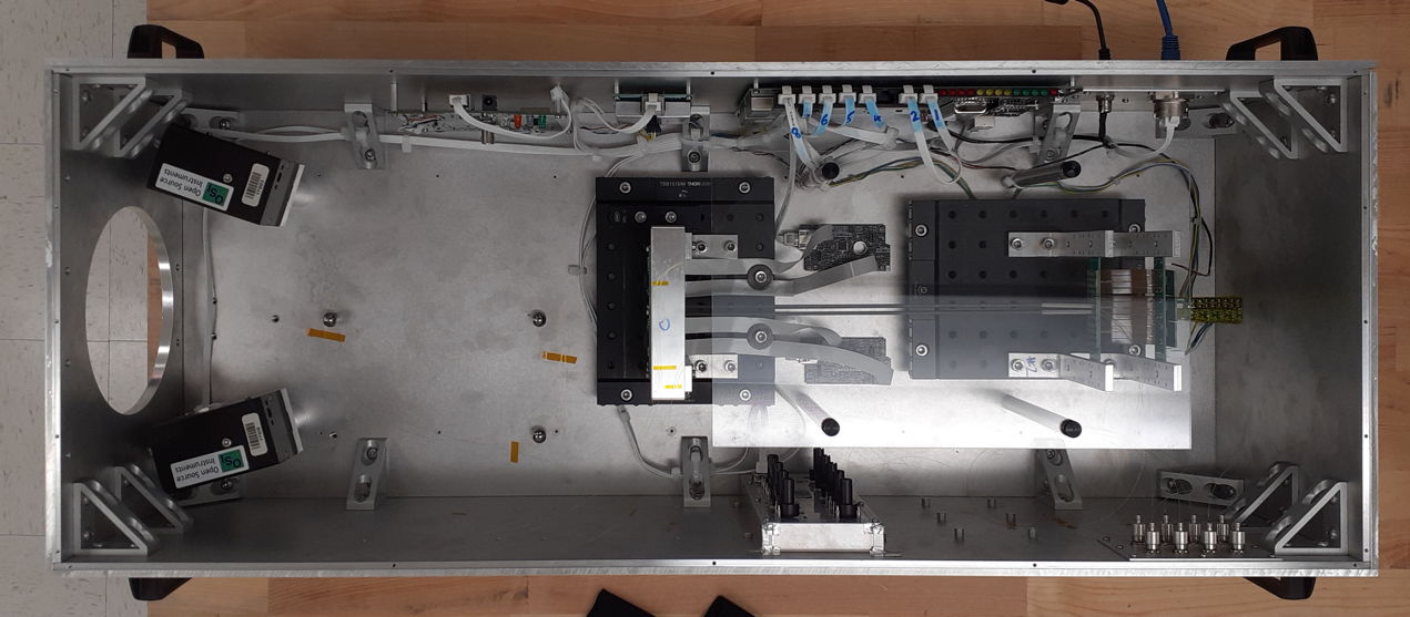
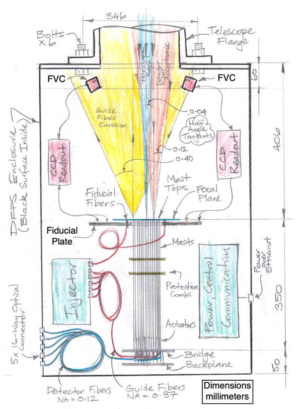
During calibration of the DFPS, we measure the location of each detector fiber with respect to its guide fiber. A pair of fiber view cameras (FVCs) within the DFPS enclosure measure the location of every guide fiber. The guide fibers have a large emission cone, so the fiber view cameras can see the guide fiber tips. The detector fibers have a small acceptance angle, so they cannot see anything except the DFPS aperture. The tips of the guide and detector fibers are inj the same plane as four fiducial fibers with large emission cones and four image sensors. During calibration, we measure the position and orientation of the guide sensors with respect to the fiducial fibers. The FVCs measure the location of the detector fibers with respect the guide sensors to an accuracy of 10 μm rms. With reference stars focused onto the guide sensors, we can deduce the location of our detector fibers in the sky.
Our DFPS Manager allows a telescope control system to acquire and read out guide sensor images. The same manager program allows us to measure the locations of guide stars in the DFPS local coordinate system, and obtain the range and current position of the detector fibers. At intervals, the manager measures the locations of positioner masts and adjusts their actuator control voltages so as to move them closer to their target positions. With a ten-second interval, this control system drives all detector fibers to within 10 μm rms of their target positions in three minutes after a movement of four millimeters. With a sixty-second interval, the control system maintains position to within 10 μm rms indefinitely, compensating for creep in the piezo-electrica actuators and changing orienation during observing.
The DFPS is the front end of a multi-object spectrograph. The back end is a system of diffraction gratings, mirrors, lenses, and image sensors that creates and records the spectra of the light from each detector fiber. We are collaborating with the Astronomical Instrumentation Laboratory at Texas A&M University (TAMU), who have decades of experience making low-cost, sensitive spectrometers.
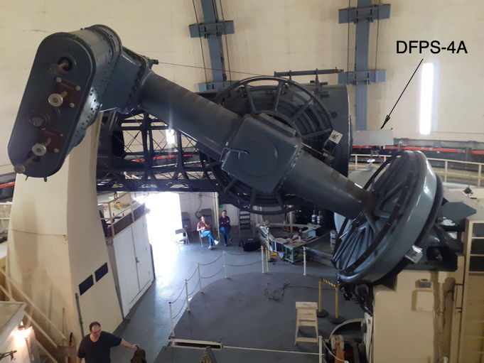
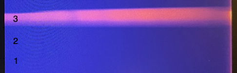
We mounted the DFPS-4A on the 2-m Otto-Struve telescope at the McDonald Observatory on 11th October 2024. On the night of 14th, we obtained our first spectrum: a forty-five minute obervation of μCygnus with the 200-μm detector fiber near the lower-left extreme of its 3.5-mm diamond-shaped patrol range. All DFPS systems fully-functional and stable.
The fiber control system holds the detector fibers in place with better than ±0.1 arcsec (±14 μm) stability while the telescope is tracking. The telescope guidance system maintains the position of stars within the field of view to better than ±0.5 arcsec. For guide sensors we picked for each observation one of the DFPS-4A's own guide sensors.
On the night of 15th October we repeated our acquisition of the spectrum of μCygnus in the same 200-μm detector fiber. We also carried out performance tests of the DFPS, measuring the movement of the fiber tips as the telescope slewed across the sky, and recording the crosstalk of red light from our guide fibers to our detector fibers. We report on these observations in our Development Page. In summary, the leakage of light from guide to detector fibers appears to be negligible and predictable, while the control system is able to control the position of the fiber tip to better than ±10 μm during tracking, including the drift in the telescope's own tracking system.
We were unable to obtain a repeatable measurement of the rotation and scale of our DFPS-4A plate coordinate system with respect to the telescope's image. We do not understand how we were unable to obtain these values, but we were hampered in our ability to make redundant measurements by the small size and high readout noise of our guide sensors. In order to make redundant measurements of plate scale and rotation we need to be able to see multiple stars at the same time, but our guide sensors could at best see one star in one sensor and one in another, which required that we find stars perfectly spaced for such an observation. Our planned DFPS-16A, which we hope to build this year, will be equipped with much larger and more sensitive guide sensors.
Our work on the DFPS between October, 2021 and April, 2023 was supported by a Phase I Small Business Initiative Research (SBIR) Grant, number 2111936, from the National Science Foundation. Integration and commissioning of the DFPS-4A at the McDonald Observatory was performed in collaboration with Texas A&M University.
[10-JUN-25] We present the following glossary of terms we use in our DFPS documentation.
| Term | Meaning |
|---|---|
| Positioner | The combination of an actuator, mast, and controller that together move the tip of a fiber. |
| Actuator | The piezo-electric cylinder that bends when we apply voltage to its electrodes. |
| Mast | The long tube that acts as a lever arm to turn the bending of the actuator into translation of the fiber tip. |
| Ferrule | A cylinder with a precision center hole that presents one or more polished fiber tips. |
| Controller | The logic, converters, and amplifiers that generate a single actuator's four electrode voltages. |
| Base Board | The printed circuit board that supports all the positioners of a single cell. |
| Service Board | The printed circuit board that holds the fiber controllers for all the positioners of a single cell. |
| Detector Cell | A base board, its fibers, its positioners, its service board, and all its controllers. |
| Detector Fiber | A fiber used to capture and transport the light from a celestial object. |
| Guide Fiber | A fiber used to reveal the location of a detector fiber. |
| Dead Reckoning | Moving a fiber to a desired position and keeping it there with no use of guide fibers. |
| Guide Sensor | An image sensor at the edge of the positioner array that records the position of guide stars. |
| Fiducial Fiber | A fiber used to locate the positioner array with respect to celestial guide sensors. |
| Fiducial Plate | The metal frame that holds the guide sensors and fiducial fibers. |
| Fiber View Camera | A camera looking down on the fiber tips. |
| Front End | The multi-object detector: fibers, positioners, and the fiber view camera. |
| Back End | The spectrometer itself: we plug the fibers into it and it records spectra. |
| Global Coordinates | A coordinate system defined by three balls on the base plate. |
| Frame Coordinates | A coordinate system defined by the front, lower-left corner of the fiducial plate. |
| Local Coordinates | A coordinate system offset from the frame coordinate origin, at the nominal center of mast positions. |
| Mast Position | The position of the mast's guide fiber tip in local coordinates. |
| Detector Position | The position of one of a mast's detector fibers in local coordinates. |
Each mast presents separate guide and detector fibers. The fiducial fibers are stationary fibers whose location we know with respect to the guide sensors.
[10-JUN-25] The DPFS-4A is based upon the eighty-positioner DFPS-80A we described in a rejected SBIR Phase II proposal. It provides only four positioners, but each positioner presents two detector fibers and one guide fiber.
The DFPS-4A moves and holds its detector fibers with 10-μm rms accuracy and stability. It overcomes the creep and hysteresis in the piezo-electric tube actuators by monitoring and adjusting the actuator control voltages. The range of each detector fiber is a square of side 3.5 mm, rotated at 45° with respect to the field of view of the fiber view cameras. The exact size of the dynamic range is not a source of great concern for us. The intended use of the DFPS is to permit each fiber to observe one object in each exposure in a sky survey, not to observe a particular object. According to our simulation, 40% coverage is perfectly adequate to permit a large-scale survey of the sky.

As detailed in our Development Log, the DFPS-4A is robust and accurate in our laboratory setting. When deployed on the two-meter telescope at the McDonald Observatory, it held its fibers stationary with respect to the telescope image plane to within ±10 μm for forty-five minute exposures. Even while slewing the telescope at full speed across its full range of declination, we see no more than a 150-μm displacement in declination, 20 μm in azimuth, and recovery to ±10 μm of target position within twenty seconds of the completion of the movement.
The DFPS provides stable fiber positioning. We have yet to demonstrate calibration of the fiber view cameras with respect to the image plane. That is: we were unable to place a fiber in the spot where our celestial map said it would be. We had to scan the fiber tip around until we found the star image. Once we find and fix whatever calculation errors are preventing our calibration from working, the DFPS will be able to move fibers onto star image automatically and keep them on the images for an entire night's observing.
[10-JUN-25] Here are further documents describing the DFPS development, design, and history.