Data Recorder (A3007)
© 2005-2017, Kevan Hashemi
Open Source Instruments Inc.
Contents
Description
Design
Performance
Description
The Data Recorder (A3007) is a LWDAQ Device that decodes and recordes subcutaneous transmitter (SCT) messagess. The A3007 takes the signal generated by a demodulator such as the Demodulating Amplifier (A3017) and determines when this signal contains a valid SCT message sequence. It stores messages in its 512-KByte memory and makes them available to the LWDAQ.
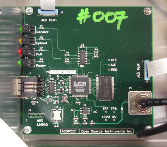
Figure: An A3007D in A3018C Enclosure. Auxilliary power sockets on top and right side are used to power RF circuits. The square logic chip is programmed throug the 8-way SIP connector. The RAM is on the right. Four indicator lamps are on the left, with the LWDAQ device socket. The discriminator comparator and RC circuits are on the bottom center, near the BNC plug that brings in the demodulated SCT signal.
The A3007 is used in the Data Receiver (A3018). The A3007A and A3007B were used in the Data Receiver (A3010). These versions are obsolete. The A3007A was unreliable because it used a ring oscillator to generate timing for the upload to the LWDAQ driver. The A3007B was equipped with a 40-MHz crystal oscillator piggy-backed onto the logic chip. Both the A and B versions are obsolete. We added a 40-MHz oscillator to the A3007C, which is shown in page two of the schematic. The A3007D has a modified discriminator filter on its input, which gives superior message decoding. Firmware version 7 fixes a severe bug in the firmware that generated bad messages in the presence of interference. Firmware version 8 adds support for higher channel numbers.
Design
S3007_1: Discriminator, LWDAQ device socket, programmable logic chip, reference oscillator, and 512-KB static RAM.
S3007_2: Second page of circuit diagram showing data clock oscillator, power distribution connectors, and indicator lamp logic. The A3007C used 10nF for C10, but in the A3007D we reduce C10 to 1nF so we can see poor reception as a reduction in intensity of D1.
Code: Directory of ABEL source and JEDEC compiled firmware.
A3010: Manual for the SCT Receiver (A3010).
A3018: Manual for the SCT Receiver (A3018).
A300701A.zip: Printed Circuit Board ZIP Archive.
A300701C.zip: Printed Circuit Board ZIP Archive.
A300701C.bom: Bill of Materials.
The A3007C used different values for the discriminator: R2=0Ω, C4=1nF, C8=0nF, and R3=51Ω. In the A3007D we return to the values we used in the A3007A and A3007B, which give better isolation of the 5 MHz bit signal for better performance with weak signals. See the Data Receiver manual for more details and here for the discriminator's frequency response, which we discuss here.
[11-JAN-13] The A3007D in A3018C assembly P0193 is giving currupted data. We investigate. It turns out that the connection between U7-78 and U6-38, which is the A14 connection to the RAM, is broken. We find that the break is somewhere between the U7-78 pad on the top side and the bottom side of a via under U7. The vias under U7 and U6 both are dull and in places have copper showing through the solder coating. We suspect that we left corrosive water-soluble flux beneat these chips and as a result, after five years, one of the tracks has been eaten through entirely. We removed both chips during the course of our investigation and cleaned the board thoroughly. We added a wire link from U7-78 to U6-38 and the board functions perfectly.
[11-JAN-13] We enhance the A3007 firmware with diagnostic options and correct what we perceive to be a couple of errors. The result is firmware V06. But the new code, despite its promise, produces a TCPIP timeout error every few hundred seconds, while Version 4 does not. So Version 6 is not ready for production.
[13-JAN-13] We go through V06 comparing it to V04 and discover a combinatorial assignation for TBL when we should have a register assignation. For some reason this does not give us a warning or error message as it is supposed to. We correct the error and try V06 again. After an hour of recording, we see no errors, so we deem it ready for use in our demonstration Data Receiver.
[11-FEB-13] We receive Data Receiver (A3018C) number Q0128 from ION. It is delivering severely corrupted data. We inspect the bottom side of the board. We see plenty of acqueous flux residue plugging the vias beneath U7. The via plating is gray. We check the connection between U7-78 and U6-38 and find it intact. But U7-80 to U6-40 is broken. We remove U7 and find the corroded vias shown below.
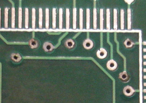
Figure: Corroded Vias. Water-soluble flux was left under the logic chip for five years.
We decide this board is not worth saving. We will build a new one.
[29-MAR-13] Assemble two A3007Ds. Both work well.
[17-MAY-13] We find a severe bug in the A3007C firmware, which we instroduced in A3007C03, back in 2007. The receiver state machine, which decodes the incoming signal bit sequence, was tolerant of a bit period of up to 130 μs, when it was supposed to be rejecting any bit period less than 250 ns. When we fixed this bug for A3007C07, the bad message rate in our basement laboratory dropped from 1/s to 0.01/s measured over all fourteen channels.
[29-JAN-14] We receive Data Receiver (A3018C) serial number P0230 back from University of Oxford. It has firmware version 4. Bad message rate in our office is 38 /min/channel. We reprogram with firmware version 7. Bad message rate is 0.5 /min/channel.