[27-JUL-22] The Implantable Sensor with Lamp (ISL) is obsolete. We have abandoned our attempts to combine sensor, stimulator, and light source into a single device. Instead, have separated them into an Implantable Stimulator-Transponder (IST), an Implantable Light-Emitting Diode (ILED), and a Subcutaneous Transmitter (SCT). We are retiring our Command Transmitter (A3029) as well, replacing it with command transmitters built into the Telemetry Control Box (A3042-B).
[01-NOV-21] Our implantable stimulators contain a micropower crystal radio that is always ready to receive commands. A stimulus command will cause the stimulator to produce voltage pulses. When these pulses are connected to an implantable lamp, they produce pulses of light. The simplest stimulation pattern, one that is provided by all our stimulators, is a sequence of n pulses, each of length τ milliseconds, and with period T milliseconds. The values of n, τ and T are part of the stimulus command. When τ = T, the lamp is on continuously for nT milliseconds. When n = 0, the pulses continue until the stimulator receives a stop command or runs down its battery. A typical stimulus for optogenetic experiments is 10-ms pulses with period 100 ms for thirty seconds.

In addition to the crystal radio, our stimulators are equipped with a message transmitter compatible with our Subcutaneous Transmitter System (SCT). The message transmitter in an Implantable Stimulator-Transponder (IST) provides command acknowledgements, battery measurements, and a synchronizing signal. The message transmitter in an Implantable Stimulator-Sensor (ISS) provides command acknowledgements, battery measurement, and biometric signal monitoring.

Our implantable stimulators use the same data acquisition hardware and software as our Subcutaneous Transmitter System (SCT), but with the addition of a command transmitter like the 910-MHz Command Transmitter (A2029C). Command acknowledgements and battery voltage measurements are transmitted by implantable stimulators as auxiliary messages, while the synchronizing and biometric signals are transmitted as data messages. Thus SCTs, ISTs, ISLs, and ISSs all operate within the same faraday enclosures and share the same data receivers.

Our implantable stimulators are equipped with lithium-polymer batteries. These batteries are the only small batteries with low enough source resistance to deliver the tens of milliamps required by implantable lamps. Between implants, we recharge the LiPo battery through the stimulator's L+ and L− leads. We cannot charge the battery while the stimulator is implanted. For instructions on how to remove an implant, recover its electrodes, and prepare it for re-implantation, see Explantation. The stimulators need special recharging circuits. The resistance of the lamp leads and the voltage drop of the internal blocking diodes makes charging with conventional LiPo chargers impossible.

In its standby state, transmitting no data and generating no stimuli, the A3030E consumes 7.7 μA from its battery. When transmitting only, it consumes 105 μA. When delivering full power delivered to an implantable lamp, the A3030E consumes 55 mA from its battery and delivers 30 mA to its LED. When driven with 30 mA, the A3024HF-B 10 mW of blue light to the tip of its optical fiber light guide. At the same current, the A3024HF-G delivers 5 mW of green light to its fiber tip. The A3030E is equipped with a 190-mAhr battery, so it can drive the lamp like this for three hours continuously. In trials at ION, we were able to provoke optogenetic circling response response in rats with 2-ms, 10-mW pulses of blue light at 10 Hz, or 5-ms, 5-mW pulses of green light at 10 Hz. (Videos available upon request.) With 2-ms pulses every 100 ms, average current consumption from the stimulator battery is around 1.1 mA. The A3030E can sustain the stimulus for 150 hours. Suppose we monitor EEG continuously, consuming 0.1 mA, and deliver 2-ms pulses at 10 Hz for four hours each day. The stimulator will keep going for around 40 days. After that, we can explant it, clean it, recharge it, and use it again. We expect each stimulator to endure several implants before its leads and encapsulation begin to show signs of wear.
The stimulators are designed to operate within one of our SCT faraday enclosures. The faraday enclosure keeps local interference from compromising reception of SCT, IST, and ISS messages, and it stops the powerful command transmission signal from interfering with local communication equipment outside the enclosure. The power of the command transmission spreads throughout the faraday enclosure, reflects off the walls, and is absorbed by the resistive foam in the faraday enclosure's ceiling.
We use the same antennas for command transmission and message reception. In a typical application, we place the transmit antenna in the middle of the faraday enclosure and two receive antennas nearer the walls. Command reception is 95% reliable in such a system, while message reception is 99% reliable. In the long run, we will increase reception to 100% by using two command transmit antennas. For now, however, the chance of a command being lost is 5%. When a command is lost, the implanted stimulator will not transmit an acknowledgment, so the stimulator system will be able to re-transmit the command or at the very least record that the command was lost.
Closed-loop optogenetic response to EEG events is performed by transmission of EEG from an SCT or ISS, reception by the data receiver, analysis by the Event Classifier on the data acquisition computer, and execution of an event handler that issues stimulus commands for a stimulator in response to EEG events. We describe this process in more detail below. By analysing the EEG in one-second intervals, this system is able to provide closed-loop control of the stimulator with an average delay of one second. The system is not capable of responding within 100 ms to a solitary ictal spike, but it can respond to seizures. In most epilepsy models, it takes four or five seconds to be certain that a seizure is beginning.
[21-FEB-20] Open Source Instruments developed the Implantable Sensor with Lamp (ISL, A3030), the Implantable Lamp (A3024HF), and the Command Transmitter (A3029) in collaboration with the Institute of Neurology (ION), University College London (UCL) in the years 2012-2017. For a history of the development, and details of its performance and efficiency, see ISL Development. Our collaborators at ION performed all in-vivo testing of the original stimulators, and provided almost all the funds required for their development. We developed a prototype Implantable Stimulator-Transponder (IST, A3036) in collaboration with the UCL in 2019. We are currently developing a Mouse-Sized Implantable Sensor with Lamp (MS-ISL), consisting of the Implantable Stimulator-Sensor (A3037A) and the Implantable Lamp (A3036IL), in collaboration with Cornell University, with funding provided by a Small Business Innovation Research (SBIR) grant awarded to us by the National Institute of Health (NIH).
[01-NOV-21] The implantable stimulator system consists of the following components, as well as cables to connect them.
| Assembly Number and Manual Link | Assembly Name | Status |
|---|---|---|
| A3036 | Mouse-Sized Implantable Stimulator-Transponder | Active |
| A3036IL | Implantable Lamp | Active |
| A3033A | Battery Charger for A3036A | Active |
| A3037A | Mouse-Sized Implantable Sensor with Lamp | In Development |
| A3015C | Loop Antenna | Active |
| FE3A | Faraday Enclosure | Active |
| A3029C | 910 MHz Command Transmitter | Active |
| A3027E | Data Receiver | Active |
| A2071E | LWDAQ Driver | Active |
| A3030E | Rat-Sized Implantable Sensor with Lamp | Obsolete |
| A3024HFC | Fiber-Coupled LED | Obsolete |
The system uses four types of cable. Radio frequency signals are carried to and from antennas by RG-58C/U 50-Ω coaxial cables with BNC plugs on either end. By default, we will supply 80-cm cables for use within faraday enclosures and 2.4-m cables for use outside the enclosure. But there is no problem increasing the length of these cables to 10 m. Shielded CAT-5 cables are used in two ways. One such cable connects the LWDAQ Driver to the internet. Two other such cables connect the driver to the data receiver and command transmitter. If we use standard, stranded-wire, shielded, CAT-5 jumper cables, these cables can be up to 10 m long. We use standard DC (direct current) power cables with 5.5-mm center-positive power plugs to deliver 24-V power to the driver and command transmitter. The 24-V power adaptors connect to AC wall power, 90-250 V, 40-70 Hz, with a standard computer power chord.
[01-NOV-21] The figure below shows how the implantable stimulator components are connected together. The implantable stimulator (IST) system is a subcutaneous transmitter (SCT) system with a command transmitter and command antenna added. Follow the SCT set-up instructions to set up the recording system for SCT messages, then add the command transmitter as shown below.
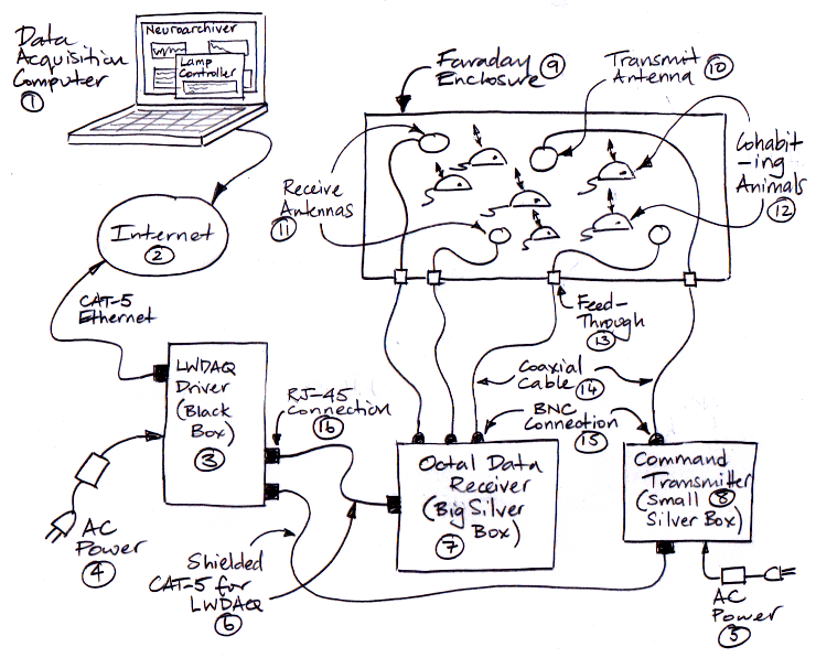
Referring to the diagram, we have the following components.
The implantable stimulator system is compatible with the SCT system, in that we can implant ISTs, ISSs, and SCTs in animals that live in the same enclosure, and receive signals from both. Only the ISSs and ISTs will be able to respond to commands.
The Command Transmitter (A3029) plugs into a Long-Wire Data Acquisition (LWDAQ) system and also receives its own 24-V power input to boost its command transmission power. When you connect the boost power supply, its blue boost light will turn on. Without the boost power supply, it will still operate, but with lower output power and therefore shorter effective range. It acts as a LWDAQ device and transmits commands to implanted stimulators through a Loop Antenna (A3015C), the same type of antenna used to pick up data transmissions from implanted SCTs, ISSs, and ISTs.
The Data Receiver (A3027) plugs into the Long-Wire Data Acquisition (LWDAQ) Driver with Ethernet Interface (A2071). The (LWDAQ) system is a data acquisition system developed for high energy physics experiments and adapted here for neuroscience biopotential recording. The data receiver acts as a LWDAQ device. The LWDAQ Driver (A2037E) connects to the global Internet, your Local Area Network, or directly to your computer via an RJ-45 Ethernet socket. You communicate with the A2037E, and therefore the Data Receiver, via TCPIP. On the computer you use for data acquisition, you run the LWDAQ software, which you can download from here. In particular, you use the Receiver Instrument, the Neuroarchiver, and the Stimulator Tool.
Note: [27-JUL-22] This guide applies to the Stimulator Tool V1, available in LWDAQ 9.1.9 to 10.4.2. The Stimulator V2+ provided by LWDAQ 10.4.3+ is for use with our new generation of stimulators, which replace all previous stimulators.
[01-NOV-21] To send commands to implantable stimulators, we use the Stimulator Tool, which is available in the LWDAQ Tool Menu. The Stimulator Tool is available in the Tools menu of LWDAQ 9.1.9+. The Stimulator Tool sends instructions to a command transmitter (such as the A3029C), and the command transmitter transmits these commands wirelessly to stimulators near its command antenna. To receive auxiliary messages transmitted by stimulators, such as acknowledgements and battery measurements, we must be downloading and displaying live data with the Receiver Instrument or downloading and recording live data with the Neuroarchiver Tool. If we want to view sensor and synchronizing signals transmitted by a stimulator, we can view them in the Receiver Instrument. If we want to view and record these same signals, we can do so with ther Neuroarchiver Tool.

The Stimulator Tool allows for one or more command transmitters, but it assumes that all command transmitters are connected to a single LWDAQ Driver. We specify the internet protocol (IP) address of that driver with ip_addr. The Stimulator Tool works with a list if devices. Each device consists of a stimulator and a stimulus. We specify the stimulator with its device identifier, id, and its command transmitter driver socket, sckt. We specify the stimulus with a pluse length, pulse_ms, a period, period_ms, and number of pulses, num_pulses. We add device to the list with Add_Device and we delete it with its own X button. Each device in the list has its own unique index, which is an integer greater than or equal to one. After working on a list for a while, we assign fresh, consecutive indeces with Refresh_List.
| Term | Meaning |
|---|---|
| Device | a stimulator paired with a stimulus, plus control buttons and state indicators |
| Device List | a list of devices, each with its labels, entries, buttons, and indicators |
| Device Index | the number we use to identify a device in the device list |
| Device ID | the number we use in command transmission to select a stimulator |
| Channel Number | the number we use in data reception to select a message |
We initiate a stimulus with the Start button. A stimulus is a sequence of pulses. We specify the pulse length with pulse_length in in milliseconds. We specify the period of the pulses with interval_length in milliseconds. The number of pulses is the stimulus length. The stimulus length can be any number from 0 to 65535. If zero, the stimulus continues indefinitely. We can stop an indefinite stimulus with the Stop command, or we can allow the stimulus to continue until the battery is nearly exhausted, at which point the stimulator will shut down, re-start, and return to its standby state. Stimulus pulses can be regular or random, according to the value of Random.
We turn on and off ISS data transmission and IST synchronizing transmission with the Xon and Xoff provided with each device. An implantable stimulator-sensor (ISS) transmits its sensor signal, and an implantable stimulator-transponder (IST) transmits its synchronizing signal, with a channel number equal to its device identifier.
Example: We implant an A3036A, serial number A213.24. We want to stimulate with one hundred 10-ms pulses with regular spacing 100 ms. We press Add_Device to create a new device. The device identifier of this stimulator is 24, so we enter 24 for id. Suppose the command transmitter is plugged into the third socket from the indicator lamps on a LWDAQ Driver. We enter 3 for sckt. We enter 10 for pulse_ms, 100 for period_ms, and 100 for num_pulses. We set the device type to A3036A. We make sure the Random box is not checked. When we press Xon, the device index will turn red to indicate that the stimulator is transmitting. When we press Start, the index background will turn green. When the stimulus should be complete, the Stimulator Tool turns the background gray again.
If we check Acknowledge, the Stimulator Tool will add an acknowledgement request to every command it transmits. After transmission, the Stimulator Tool looks in the Receiver Instrument's auxiliary message list for the requested acknowledgement. If it does not find the acknowledgement within a timeout period, it issues a warning and turns the device index orange. Acknowledgment monitoring requires live data acquisition with the Receiver Instrument. When the Verbose flag is set, the Stimulator Tool prints the command bytes it sends to the command transmitter, and notes the acknowledgements it receives.
The Battery button sends a battery voltage instruction to the selected stimulator. The stimulator should respond with a battery voltage message. Provided we are downloading data continuously with the Receiver Instrument, the Stimulator Tool will extract battery voltage messages from the Receiver Instrument's auxiliary message list. When the Stimulator Tool obtains a battery voltage reading from a stimulator, it reports the reading in these indicators. When the battery voltage is above blow, the indicator is green. When it drops below blow, the indicator turns orange. When it drops below bempty, the indicator turns red. By default blow = 3.6 V, bempty = 3.2 V.
The Start_All, Stop_All, Xon_All, Xoff_All, and Battery_All buttons transmit the named command for every device in the list, one after the other. The time taken to send each command will be of order ten or twenty milliseconds. If we want to send a single command to all transmitters within range of a single command antenna, we can use the wildcard character, "*", in place of the device id in one of the device definitions. With a wildcard in place of the identifier, the command that is transmitted will not contain an identifier selection, and all stimulators in range will respond to the command. In this way, we can initiate the same stimulus in all devices at exactly the same time. The Stimulator Tool disables its aknowledgement monitoring for all wild-card commands, because the acknowledgements will all be transmitted at the same time, and therefore they will most likely collide with one another, so the fact that they fail to appear is not significant.
The acknowledgment and battery report messages are SCT auxiliary messages. If we are downloading messages continuously from a data receiver with the Recorder or Neuroarchiver, the Stimulator Tool will extract these messages from the incoming message stream and look for acknowledgements it expects to receive. When an acknowledgement is not received, either the command was not received by the stimulator due to inadequate command power reaching its antenna, or the acknowledgement was transmitted but not received by the data receiver's antennas. With two or three antennas in the same enclosure as the stimulator, the likelyhood of an acknowledgement being lost is less than 2%. The likelyhood of a command being lost is closer to 5%. In either case, re-transmitting the stimulus command is almost certain to ensure the stimulus starts.
[26-FEB-20] At present, our stimulators support only a simple stimulus format: pulses of the same duration, with a fixed period, and lasting for a specified number of pulses. Nevertheless, the Stimulator Tool allows us to define multiple stimuli for the same implanted stimulator, so we can easily deliver a variety of these simple stimuli so as to contruct a more complex stimulus.
In addition to regularly-spaced pulse stimuli, the stimulators support randomized pulses with an average pulse rate that is close to that of the same stimulus's non-random pattern. The Random check box in each device of the Stimulator Tool's device list allows us to turn on the random pulse generator. When pulses are random, the pulse length is always the same, and the average time between pulses is approximately equal to the interval length. But the time between individual pulses varies.

The average number of pulses per second in the random stimulus is not exactly the same as in the regular stimulus with the same value of period_ms. The average frequency is slightly less. In the example above, we get 9.3 pulses/s on average for a requested frequency of 10 pulses/s.
[26-FEB-20] One use of a stimulator is to allow us to detect particular events in a biopotential signal and respond to them with stimuli. This detection and stimulation process is what we call closed-loop response. All our stimulators support external closed-loop response, in which we transmit the biopotential with a subcutaneous transmitter, decide externally to the animal when to begin a stimulus, and transmit the stimulus command to the stimulator from outside the animal. But the logic chip on board our stimulators is capable of supporting internal closed-loop response, in which the stimulator itself detects events and responds to them with stimuli. At the time of writing, the firmware required for internal closed-loop control is not yet available.
We implement external closed-loop response by transmitting a biopotential signal from an ISS or SCT, recording the signal with the Neuroarchiver, detecting events as they occur with the Event Classifier, and instructing the Command Transmitter to send a command to the stimulator when a particular sequence of events is detected. The stimulator generates the stimulus in response to the command.
The Neuroarchiver divides the incoming signal in to intervals of fixed length. It processes each interval as it becomes available. Let us assume the intervals are one second long, this being a suitable length for seizure detection. And let us refer to the signal as EEG, even though we could equally well apply event detection to EKG, EMG, or any other biopotential signal. When a new one-second interval of EEG arrives from the ISL, the Event Classifier compares the new interval to a list of intervals that we have previously classified with our own eyes, a list we call our event library. The Event Classifier finds the member of our event library that is most similar to the new interval. Provided this previously-classified event and the new interval are similar enough, and provided the new interval meets a minimum power requirement, we assume the new interval to be of the same type as the previously-classified event. The classification of the new interval might be "Ictal", "Spike", or "Baseline". If the new interval is unlike any in the event library, it will be "Unknown". If it does not meet the minimum power threshold, it will be "Normal".
Having classified the new interval, the Event Classifier calls an event handler. The event handler uses the classification of the new interval, and the history of classification of the same signal, to deterine what action to take. The event handler could, for example, look for three consecutive ictal intervals, and then initiate the stimulus defined by a particular Stimulator Tool device. Here is an event handler that starts the stimulus defined by Stimulator Tool device number three (3) when the Event Classifier detects an event of type "Ictal". To use the handler, we must have the Stimulator Tool open, so that device number three (3) will be defined.
set info(handler_script) {
    if {$type == "Ictal"} {
        Stimulator_start 3
    }
}
If we are to implement internal closed-loop response in the ISL, we must use efficient metrics to represent the features of each interval. Use of the Fourier transform would be too computationally intensive for use inside the ISL. Our ictal event detectors, such as ECP19, are designed to be computationally efficient. They do not use the Fourier transform. Instead, they rely upon non-linear, efficient metrics. The firmware and software required to give the ISL on-board event detection will take roughly five hundred engineering hours to bring to maturity. One day we hope to find the time to implement a microprocessor in the ISL and so provide autonomous, event-driven stimulus, in a single, fully-implantable, long-lived device.