Figure: A3016SO Output Frequency vs. Temperature. The SAW filter is the B3563, whose pass band is 864±4 MHz.
The RF Combo (A3016) is a combination of three circuits. Its purpose is to provide circuit boards for Stage Four of our subcutaneous transmitter development. The printed circuit board has the same outline as the RF Tester (A3014).
The three circuits combined on the A3016 are listed below.
| Version | Description |
|---|---|
| A3008C | Spectrometer |
| A3016SO | SAW Oscillator |
| A3016DR | Demodulating Receiver |
The SAW Oscillator (A3016SO) replaces the A3014SO. This new version uses unconditionally-stable amplifiers and other improvements. It is the same shape and size as the A3014SO.
The RF Spectrometer (A3008C) replaces the RF Spectrometer (A3008C). This new version eliminates the poorly-performing SAW filter self-calibration system, and replaces it with a local oscillator output connector that will allow us to calibrate the spectrometer's local oscillator with respect to a SAW Oscillator reference. It is the same shape and size as the Data Recorder (A3007C).
The Demodulating Receiver (A3016DR) replaces the A3014DR. This new version uses unconditionally-stable amplifiers in the RF input stages, so as to avoid oscillations provided by the SAW filter outside its pass-band, and by antenna cables. Its IF amplifier cannot damage itself when over-driven. We use attenuators between IF amplifier stages in the hope that these will guarantee stability in the face of limiting gain. We add a low-pass filter to the demodulated output to get rid of the second harmonic of the IF. We add a final buffer to produce a large 50-Ω output.
In our experiments, we made extensive use of our new set of coaxial attenuators, in Minicircuit's HAT-series.
S3016_1: LWDAQ Interface of RF Spectrometer (A3008C).
S3016_2: Downshifting Receiver of RF Spectrometer (A3008C).
S3016_3: SAW Oscillator (A3016SO).
S3016_4: Demodulating Receiver (A3016DR).
The SAW Oscillator (A3016SO) works well. We were at first confused by it because it would not oscillate with any or our narrow pass-band filters, such as the 868.4±1 MHz B3570, which we used to produce our reference frequency with the A3014SO. But the A3016SO does oscillate with filters whose pass bands are a few megahertz or more. And when it does oscillate, the A3016SO is stable and robust. We can stop it oscillating by touching the circuit, but we cannot provoke parasitic oscillations. The amplifiers are unconditionally stable. The output power remains unchanged if we remove the bias inductors. We substitute solder-lumps for the coupling capacitors on either side of the SAW filter.
| Part | Nominal Pass Band (MHz) | Package |
|---|---|---|
| AFS869S3 | 865.0-873.0 | 3.8-mm |
| AFS915S3 | 911.5-918.5 | 3.8-mm |
| AFS916.5S3 | 913.0-920.0 | 3.8-mm |
| B3563 | 862.5-865.5 | 3.0-mm |
| B3570 | 867.4-869.4 | 5.0-mm |
| B3574 | 867.3-869.3 | 5.0-mm |
| B3588 | 902.0-928.0 | 3.0-mm |
Below is a table of the output frequencies we obtained for various SAW filters. We mix the A3016SO output with our 868-MHz A3014SO reference circuit, and look at the IF with our oscilloscope. We give the A3016SO output frequency with respect to the reference frequency. When the sign of the frequency was in doubt (868+4 MHz or 868−4 MHz), we resolved the ambiguity with the help of our 910 MHz reference A3014SO. For comparison, here is a simiilar table for the A3014SO. The table includes the use of capacitors, inductors, and solder lumps for the filter coupling.
| SAW | Coupling | IF (MHz) | RF (MHz) |
|---|---|---|---|
| B3563 864±4 MHz | 0Ω/0Ω | -4.5 | 864 |
| B3563 864±4 MHz | 10nH/10nH | NO | NO |
| B3563 864±4 MHz | 10nH/0Ω | NO | NO |
| AFS915S3 915±3.5 MHz | 0Ω/0Ω | +28 | 896 |
| AFS915S3 915±3.5 MHz | 10nH/0Ω | +60 | 928 |
| AFS915S3 915±3.5 MHz | 10nH/10nH | +51 | 919 |
| AFS915S3 915±3.5 MHz | 0Ω/10nH | +60 | 928 |
| AFS915S3 915±3.5 MHz | 10pF/0Ω | +28 | 896 |
| B3570 868.4±1 MHz | 0Ω/0Ω | NO | NO |
| B3574 868.3±1 MHz | 0Ω/0Ω | NO | NO |
Both the A3014SO and the A3016SO oscillate with the AFS915S3. We expected to be able to vary the oscillation frequency of the A3014SO between 902 MHz and 928 MHz by adjusting its coupling networks, but we succeeded only in a variation of 900-910 MHz. The A3016SO gives us frequencies from 896 MHz to 928 MHz. Because the A3016SO won't oscillate with any of our narrow-band SAW filters, we still need the A3014SO, with its unstable, oscillation-happy amplifiers to provide us with our ultimate ±1 MHz frequency reference.
When we change the ERA-3SM for a MAR-6SM amplifier, the circuit still works, and the frequency of oscillation with the B3563 does not change. The A3016SO with the B3563 filter gives us a reliable 864-MHz, which is the frequency our Demodulating Receiver's (A3016DR) requires for its local oscillator input.
We attach a temperature sensor to our A3016SO, near the ERA-3SM and SAW filter, read it out with a A2053, cooled the board with freezer spray, and watched how the output frequency changed. We want our LO frequency to be stable as our circuit heats up and cools down. The frequency drops by approximately −0.1 MHz/°C, which is negligible when compared to the variation in A3013 transmission frequency of −4 MHz/°C.
We applied the A3016SO output to the LO input of the ADE-2ASK mixer on our A3016DR. This mixer's conversion loss is 7 dB for +10 dBm LO, 7.5 dB for +7 dBm LO, and 8 dB for a +4 dBm LO. We observe the same relative changes in conversion loss when we insert 3 and 6-dB attenuators in series with the A3016SO output. The output for 0-dB attenuation is the same as the output we get when we apply 10 dBm using our A3014SO. We conclude that the A3016SO output is roughly +10 dBm.
We measured the power as described below. We used our A3014SO with a −6-dB attenuator as a source of LO for our ZAD-11, and applied our A3016SO output through a 12-dB attenuator to the RF input. The IF output was −11 dBm, which puts the output of the A3016SO at around +9 dBm.
A few weeks later, we discovered that our 864-MHz A3016SO became unstable when we plugged an A3007C into the LWDAQ driver. We don't know why that's the case, but we note that the A3016SO uses +5V for its amplifiers, and the A3007C uses +5V to power all its circuits. Better decoupling of the +5V supply may solve the problem, but a 10-nF capacitor across C112 did not solve the problem.
We replaced L104 with a 0-dB attenuator. The output frequency remained 4.3 MHz below our 868-MHz reference A3014SO. The output power remained the same. The oscillator remained stable when we connected the A3007C to the LWDAQ. We tried the B3574 SAW filter in the modified A3016SO, just to see if it would oscillate after these changes, but it didn't.
We built two more A3016SOs with the B3563 SAW filter. The new ones worked right away, and were just as stable as the first. The oscillation frequencies of the three were all within 500 kHz of one another, or 864±0.5 MHz. Their output power, measured with the method described below, were 10.5±0.5 dBm.
[08-OCT-08] We observe that our 864-MHz A3016SO power output drops to as low as 6 dBm when the +5V supply on the A3016SO drops to 4.5 V. At 4.6 V and the power output increases to 8 dBm. The gain of the ERA-3SM amplifiers we use in the A3016SO drop rapidly when the supply voltage drops below 5 V. We used a 5-V supply because we wanted to save power.
[08-MAY-13] The B3563 oscillates in the A3016SO position L101. The total track length from the output of U101 around to its input is 125 mm. These 30-mil tracks are 15 mil above the ground plane, so their characteristic impedance is 50-Ω and their wave velocity is 175 mm/ns. At 900 MHz, they introduce a delay of 2.0°/mm. A 125-mm length creates a phase shift of −250°. The ERA-3SM introduces a phase shift of +80°. Adding these together we get −170°. The B3563 does not oscillate in the A3014SO position L1 position, where the track length is 85 mm, for −170°, and the UPC2746 introduces a phase shift of −150°. Adding these we get +40°. These observations suggest that the phase shift of the B3563 is 170° at 864 MHz. In the A3016SO this phase shift combines with that of the remainder of the feedback loop to give 0°. But in the A3014SO, the result is 210°, which is very var from the 0° required for oscillation.
[19-MAR-14] We measure the LO frequency of the A3016SO in A3018 P0247 and P0232 and find it to be 864 MHz in both circuits. The ciruits are marked 862 MHz. Both are equipped with the B3563 SAW filter.
The RF amplifier of the A3016DR, consisting of amplifiers U201 and U202, was a success. At first it oscillated. But after many experiments, we eliminated the two bias inductors and the oscillations stopped. We increased the supply voltage for the RF amplifiers from 5 V to 15 V, and used two 160-Ω to resistors to provide bias, instead of one 50-Ω resistor. The schematic now shows the inductors and resistors as 160-Ω, and +15V power supplies. The RF to IF Gain, which we define as the gain from the RF input to the IF output, increased by 5 dB.

We removed C203 and C204, the 100 pF coupling capacitors on either side of the SAW filter, and replaced them with solder-lump shorts. This increased our RF to IF gain by 3 dB. The SAW filter has no DC path to ground, and so requires not decoupling. As we later discovered the SAW filter does not perform well when it is AC-coupled on both sides. As least one side should be DC-coupled.
We connected a Loop Antenna (A3015L) on the end of a 96" RG-58U/C cable to the RF input of our amplifier, and observed stable reception from a quarter-wave wire stuck in the BNC output of our 910-MHz A3014SO.
We now applied the −8 dBm output of our Modulating Transmitter (A3014MT) through a 30-dB attenuator and 1-dB loss 1-m cable to the RF input of our A3016DR. As a source of LO, we used our 864-MHz A3016SO. With the IF frequency at 46 MHz, the RF frequency is 910 MHz. We observe the output power to drop with more RF attenuation, and rise with less. We assume that neither stage of the RF amplifier is saturating. We removed the SAW filter using our bypass track, as shown here.
The IF signal was 180 mV p-p, or −11 dBm. The input power is −39 dBm. From this we conclude that the gain of the RF amplifier at 910 MHz is 27 dBm. If we assume a 7-dB loss in the mixer, and a 1-dB loss in the IF low-pass filter, we see that each amplifier is providing around 18 dB of gain.
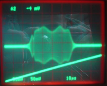
We now swept the frequency of the RF input by applying a triangle wave of 0 V to 1.5 V to the TUNE input of the A3014MT.

The cut-off we observe at the top end is due to the IF low-pass filter, which rejects IF frequencies higher than 70 MHz. We put the SAW filter back in the RF amplifier path, and removed the unnecessary coupling capacitor.
As you can see, the response drops off at the same place on the top end (to the right). This is because the SAW filter cut-off occurs at a higher frequency than the low-pass filter cut-off. The response drops off at the low end (to the left) because of the SAW filter cut-off. The low and high-end TUNE voltages are approximately 0.4 V and 0.9 V.
We set the TUNE voltage to 0.4 V. The IF frequency was 29 MHz, corresponding to an RF frequency of 893 MHz. With TUNE equal to 0.9 V, the IF frequency was 70 MHz, corresponding to an RF frequency of 934 MHz. Our RF amplifier's pass-band, when we include the effect of our IF low-pass filter, is 893 MHz to 934 MHz, with gain in the 902−928 MHz ISM band constant to ±1 dB. We are very pleased.
We also note that the amplitude of the response does not drop when we add in the B3588 SAW filter. Indeed, the IF amplitude at the lower end of our pass-band increases slightly. This surprises us, because the B3588 is supposed to have a pass-band insertion loss of 3 dB. We conclude that our 100-pF coupling capacitor is introducing a loss of 3 dB.
When we re-calculate the gain of each amplifier stage, including a 3-dB loss in the SAW filter, we conclude that each stage is producing 20 dB of gain.
Our IF amplifier was a failure. Even after removing all the amplifier bias inductors, the second and third stages always oscillated.
The first stage works on its own, with an ERA-3SM for U203. But we could not stop oscillations in the subsequent stages, even after removing the bias inductors. We hoped that the addition of attenuators would stop such oscillations, but they did not. We tried capacitors across the IF amplifier bias resistors, thinking this would cut down the high-frequency gain and stabilize them, but these capacitors served only to provoke oscillations at lower frequencies. We observed oscillations between 100 kHz and 50 MHz at various times during our experiments, and we often saw signs of 700 MHz oscillations as well.
We made many conflicting observations of signal amplitude and attenuation using our oscilloscope probe. For a while we believed that our problems was parasitic inductance in our capacitors. But we later found out that we were suffering all the time from oscillations in our RF amplifier that stopped when we removed AC-coupling on both sides of the RF amplifier's SAW filter. It may be that our efforts to stabilize the IF amplifier were thwarted by the instability of the RF amplifier
Even if we could stabilize the IF amplifiers, we observed that they do not saturate in at a well-defined power output. Uniform saturation is essential for our frequency demodulation, so these amplifiers are not suitable for our limiting IF amplifier.
We resolve to go back to the OPA699 limiting op-amps we used in the A3005. But we note that the A3005 used one IF stage with a MAR-6SM amplifier, and we many times observed this stage to be unstable. It would oscillate if we touched it with a probe, and one of them would oscillate when we put it in a metal box. We conclude that the A3005 could not have been performing well, and we hope for better performance from our next design, the Demodulating Receiver (A3017).
When we removed C203 and C204 on either side of the SAW filter, and replaced them with solder-lump short, our RF to IF gain rose by 3 dB. This suggested that loss was occurring in our coupling capacitors. We left C204 as a solder-lump short, and tried various capacitors in the place of C203 or C204 in our RF Amplifier. We applied −35 dBm of 910 MHz to our RF input, and +9 dBm 864 MHz to our LO input. We measured the IF amplitude, and so determined the loss introduced by each capacitor.
| Capacitance | Part Number | Loss When C203 (dB) |
Loss When C206 (dB) |
|---|---|---|---|
| 0 pF | Open Circuit | >30 | >30 |
| 10 pF | AVX 08052A100JAT2A | 0 | 0 |
| 47 pF | AVX 08051A470KAT2A | 0 | 0 |
| 47 pF | Murata GQM1885C1H470JB01D | 0 | 0 |
| 100 pF | Panasonic ECJ-2VC1H101J | 0 | 0 |
| 100 pF | Murata GQM1885C1H101JB01D | 0 | 0 |
| 1 nF | TDK C2012X7R1H102K | 0 | 0 |
| 10 nF | TDK C2012X7R1H103K | 0 | 0 |
| 100 nF | Unknown | 0 | 1.2 |
| 1 μF | Murata GRM31MF51E105ZA01L | 0 | 0.8 |
Only the 100-nF and 1-μF capacitors introduced any measurable loss. This suggests that the impedances of all other capacitors are less than 10 Ω at 910 MHz. According to this report, the parasitic inductance of a P0805 package is around 1 nH, which would present and impedance of 6 Ω at 900 MHz. So each of our capacitors appear to approach this 1 nH intrinsic limit to their parasitic inductance. In that case, their impedance will vary with frequency as shown here.
These results appear to contradict our earlier observation that replacing C203 and C204 with solder-lump shorts increased our RF to IF gain by 3 dB. So we restored our 100-pF capacitors to C203 and C204. Our IF output was distorted, and we lost over 3 dB of gain. We conclude that the SAW filter does not perform well with AC coupling on both sides. But it does well with AC coupling on one side or neither side.
As described above, we removed the SAW filter from our RF Amplifier and replaced it with a single 100-pF decoupling capacitor. Our RF to IF gain dropped slightly at 900 MHz and remained constant at 930 MHz. If we can trust the SAW filter data sheet, it has an insertion loss of 3 dB. Therefore the 100-pF capacitor must have introduced a loss of 3-dB also.
We are now waiting for some RF capacitors so that we can see if by-passing the SAW filter with a decoupling capacitor will reveal the imperfections of general-purpose capacitors at 900 MHz.
Even with capacitors that show the minimum parasitic inductance for their packages, we might further improve our power supply decoupling by taking advantage of the series resonance between a capacitor and its parasitic inductances. The following graph shows series resonant frequency versus capacitance for Murata's high-frequency GQM-series capacitors. It appears that 47-pF GQM capacitors will resonate at 915 MHz, and we can therefore expect their impedance to be less than 1 Ω in the 900-MHz ISM band of frequencies.
Despite these pleasant, theoretical predictions, our table above shows no improvement in coupling performance by 47 pF over any other value. We see no difference in coupling performance between general-purpose P0805 and high-frequency P0603 capacitors, even though the former cost 10 ¢ each, and the latter $1 each.
When it comes to decoupling performance, however, we do see a difference between the GQM-series capacitors and the general-purpose capacitors. In our discussion of the Modulating Transmitter (A3014MT), we show how the GQM capacitors acting as decoupling for a MAX2624 VCO give us the largest VCO output power. And we see the 47-pF capacitor performing better than the 100-pF and 22-pF capacitors as well.
We conclude that our P0805 capacitors up to 1 nF all have parasitic inductance of order 1 nH, and perform well at 910 MHz. The 100 nF capacitor shows some loss, as does the 1 μF, but neither has impedance greater than 20 Ω at 910 MHz. When it comes to coupling in 50-Ω signal paths, general-purpose 1000 pF capacitors work just as well as high-frequency 47 pF capacitors. But we gain by using 47-pF high-frequency capacitors to decouple power supplies.
See the RF Spectrometer manual for a description of the A3008B.