| Introduction |
| History |
| Conclusion |
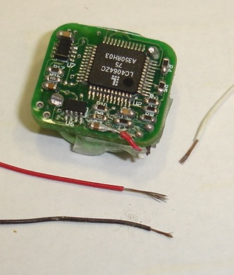
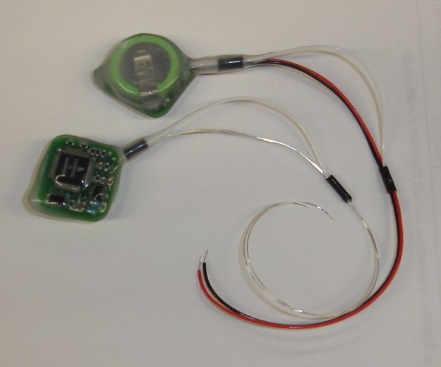
[18-MAR-26] This document records the development of a reliable, corrosion-resistant encapsulation for our Subcutaneous Transmitters (SCTs). We use the same process to encapsulate our Implantable Stimulator-Transponders (ISTs), Blood Pressure Monitors (BPMs), Implantable Inertial Sensors (IISs), and Intraperitoneal Transmitters (IPTs). The process requires no mold, and is easily adapted to new shapes and sizes of implant, provided you have the necessary vaccum and rotation apparatus to support the process, and provided that you are sufficiently skilled at cleaning and inspecting the circuit boards. The process must be backed up by accelerated aging of 10% of the devices encapsulated. We place one in ten of the devices we encapsulate in water at 60°C and run them until they stop. By this means, we monitor the corrosion resistance of the encapsulated devices. Eposy and silicone are permeable to water vapor. Eventually, the device will corrode. At the time of writing, the corrosion resistance of our encapsulated devices is at least 300 days at 37°C (30 days at 60°C). Note that we do not describe in detail our current encapsulation process in this document or any other on our website. Instead a series of precursor processes, and we conclude with an overview of the current process.
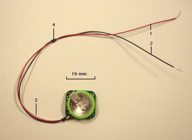
An animal's body is filled with saline at 37°C. Water vapor penetrates throughout a silicone and epoxy encapsulation within a few days at this temperature. This water vapor will eventually condense in any cavities within the silicone or epoxy. Our concern is particularly with the epoxy, because it is epoxy that surrounds our components. If there are cavities beneath the components, or on the surface of the circuit board, they will become electrically conducting. Current will flow and metal will start to micrate from the component pads, eventually causing low-resistance conductive paths. Within capacitors, microscopic cracks will become wet and start to corrode, eventually causing a short-circuit between the capacitor plates that will draw current in erratic bursts. We must avoid cavities in the epoxy. We must make sure no flux remains on the boards. We must make sure the capacitors are handled with the utmost care during assembly.
[17-APR-2007] Copper is commonly used for plumbing. In theory, it will resist water. But acidic or alkaline water may be able to corrode it, and corrosion can accelerate when there is a voltage across the copper terminals. We examined the wires of our immersed transmitter after a weeks in water. These had 1-V across them due to damage that had taken place in the circuit (see below).

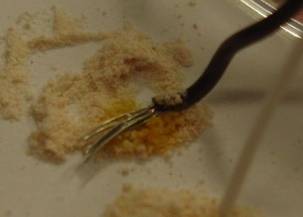
After a week in water, a green participate powder had appeared around the exposed copper of the transmitter's lead wires. Our guess is that this powder is copper (II) carbonate. Copper reacts with water and carbon dioxide like this:
2Cu(s) + H2O(g) + CO2 ---> Cu(OH)2 + CuCO3(s)
The beaker we used was the same one in which we soaked coated transmitters in silicone eater, and prior to that, it was used for cleaning circuits in dichloromethane. The transmitter we used for this corrosion test was damaged in the manner described below. It applied 1 V across the red and black wires.
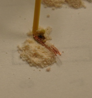
After a week, tinned copper surfaces that were shiny when we first dropped them into our water beaker were now dull and patchy. Nevertheless, they are still perfectly functional. We conclude that, even in adverse conditions of applied voltage and impure water, our tinned copper wires will resist corrosion. We expect them to resist the fluid environment in an animal's body.
As we describe below, we immersed an un-damaged silicone-coated transmitter in 200 ml of water for three days in the same beaker. We saw no sign of corrosion on either of the tinned copper leads. Both were shiny. We put 3 g of salt in the water and waited to see what would happen.
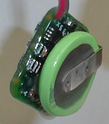
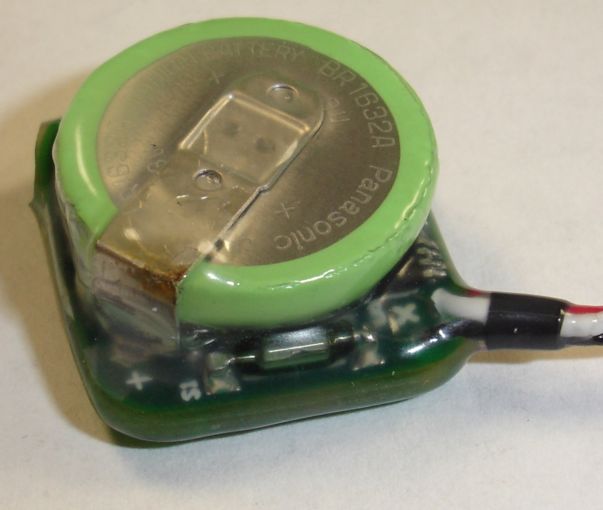
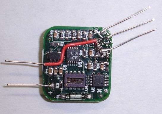
[28-MAR-2007] We discussed epoxy encapsulation, or potting, with David Christiansen of Ellsworth. He recommended that we try the EP965 two-part epoxy casting resin by Resinlab. We made a teflon mold with a rounded bottom and an open top. We soldered a battery onto a blank transmitter board, along with a 32.768 kHz clock oscillator running off the battery. We soldered wires to the battery leads, and to the output of the clock. We took out a retired A3009 transmitter with a dead battery, and soldered a single antenna wire to it. We used these as dummy circuits upon which to test our irreversible epoxy-encapsulation process. Below is a picture of the mold with the two dummy circuits. The epoxy has dried.
The battery and clock oscillator in the active circuit appeared unaffected by the potting process. We observed the oscillator output and battery voltage before, during, and after the curing period. When we extract the circuits from the mold, they have sharp edges around the top. These we can file down easily with a metal file, until all edges of the transmitter are smooth.
We see no gaps in the encapsulation. There are some cavities around the black wire on the inactive circuit, but these do not appear provide any path for moisture into the circuit. Neither circuit made contact with the side of the mold through the epoxy. We were concerned that the circuits would rotate in the mold and so end up protruding from the encapsulation. But surface tension restrained both circuits well within the body of the epoxy, and we have at least 0.5 mm of covering all around the circuit on all sides.
This initial mold produces encapsulated circuits 20 mm × 19 mm × 10 mm. They weigh 5.5 g, and their volume was 3.8 ml. The A3013 printed circuit board itself is only 18 mm × 16 mm, and the height of the entire circuit with battery is only 7 mm. We think it likely that we can reduce the size of the mold to 19 mm × 17 mm × 8 mm (volume 2.6 ml), leaving 0.5 mm on all sides for the encapsulate, and trusting to surface tension to keep the circuit from penetrating through the encapsulate to the mold sides. With the smaller mold, the circuits will weigh only 4 g.
The resistivity of the EP965 epoxy is, according to its data sheet, 8×10¹⁴Ω-cm. A 1-mm cube of resin will present a resistance of 1015Ω. We expect no battery drain due to conduction through the epoxy.
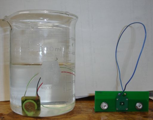
We placed the active circuit in water on 28th March 2007, and monitored its battery voltage and 32.768 kHz clock signal until 2nd April 2007. We saw no change in battery voltage or clock signal amplitude. We conclude that the encapsulation is entirely waterproof.
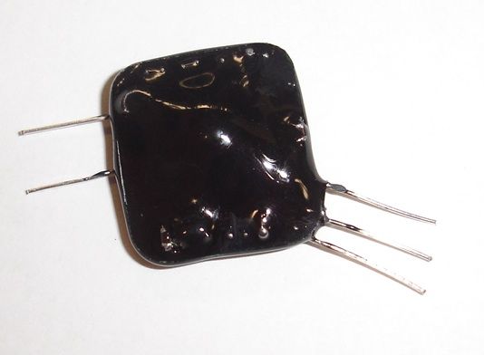
We encapsulated one transmitter in clear epoxy and one in black epoxy. After 18 hours, we removed both from the mold. The broken transmitter one had a single cavity on the side of the black epoxy encapsulation. This cavity was a bubble trapped between the battery and the mold wall. The other transmitter was well-encapsulated. We filed down the sharp edges, but filed too much off the bottom side, exposing some battery metal and the printed circuit board ground plane. We put both transmitters back in the mold with a fresh dose of epoxy. The next day, we found the newer epoxy was well-bonded to the original epoxy. The cavity in the black transmitter was gone, and the metal on the viable transmitter covered over. The figure below shows both transmitters.
We dropped our clear-encapsulated two-channel transmitter into a beaker of water. The transmitter operated continuously in water for a week.
[23-APR-07] On Matthew Walker's recommendation, we bought som MED10-6607 silicone dispersion. From our local hardware store, we bought clear bathroom Silicone II caulk. We also made use of a silicone-eating compound, SU100.
We applied three coats of silicone dispersion to two transmitters. We held the transmitter by its wires, dipped it in the dispersion for sixty seconds, and hung it up to cure for at least an hour before applying the next coat. We took photographs after each coating: One Coat, Two Coats, and Three Coats. The third photograph shows the gab between the transmitter and the battery. This gap is unfilled, and the components inside the gap appear to be poorly-coated. The figure below is a close-up of the gap.
We injected the dispersion between the battery and the board, so that the parts between the gap would receive a good coating. For a photograph, see here. We were careful not to short any electrical connections with the metal syringe tip.
After we injected silicone dispersion into the gap, we dipped both transmitters into the dispersion for a fourth time, and hung them up to drip and cure. We left them over-night because previous experience taught us that the dispersion hidden in the gap dries out slowly.
The next morning, the transmitters look like this. Note the large drop of silicone at the bottom corner. The coating is still inadequate on one edge next to the wires, in between the battery and the circuit board. The other edge next to the wires has the reed relay filling the gap between the battery and the board, and the silicone covers the relay and the battery.
[26-APR-07] We injected more silicone dispersion in the gap between the battery and the circuit board, and left the transmitters standing upright on a piece of paper. For a photograph, see here. After a few hours, we injected some more dispersion into some remaining gaps. The next day, we cut off the drop at the bottom of each transmitter (you can see the drop here) and dipped them for a fifth time. In the afternoon they looked like this. If you look closely at the photograph, you will see air bubbles trapped under the fifth coating. We found no gaps in the coating when we examine both transmitters through our ×7 loop.
We washed the transmitters in alcohol (we had been handling them with our fingers) and coated them a sixth time. After an hour, the coating is hard enough to handle. Three hours later, we took the photograph below.
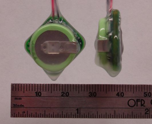
As you can see from the photograph, the coating is lumpy in places. The transmitters are not rectangular in cross-section: the circuit board is the widest part, but it is also the thinnest. The average dimensions of the coated transmitters are roughly 17 mm × 17 mm × 8 mm. Their volume, which we measured by water displacement, is 2.0 ml. This volume does not include the volume of the lead wires. The transmitter without its wires weighs 4.0 g. The wires add another 0.4 g, making the total weight 4.4 g. In our Technical Proposal, we quoted our target weight for the transmitter without wires as 3 g, with target volume 2.0 ml. Our transmitter turns out to be slightly more dense than we had hoped.
The next day, the coating was resilient and smooth. We dropped the transmitters in water and left them there for several days. They show no sign of losing power.
While experimenting with silicone coatings, we were plagued by the random failure of transmitters described elsewhere. This failure had nothing to do with the coating. As a result of the failures, we ended up with broken transmitters encapsulated in silicone. We removed the silicone in the following way. First, we pulled as much of it off as we could with tweezers and pliers. Second, we soaked them in SU100 silicone-eater for two days. During the two days we twice picked up the individual transmitters and brushed them with a toothbrush. After two days, we washed the transmitters in water and scrubbed them again with a toothbrush.
With the silicone removed, we were able to refurbish the transmitters. Cleaning them thoroughly after removal is essential for reducing their quiescent current. We had to measure and re-clean until the quiescent current was low enough. The entire process took approximately one hour of engineering time per transmitter in a fully-equipped lab.
Transmitters failed in all three of our encapsulation methods. We believe that these failures were due to electronic problems, not water penetration. We decide to pick either silicone or epoxy encapsulation for more rigorous tests in saltwater. We base our decision upon the following comparison of the two methods.
| Feature | Silicone Dispersion | Casting Epoxy |
|---|---|---|
| Substance | MED10-6607 | EP965 |
| Texture | smooth and rubbery | tacky and hard |
| Edges | smooth and yielding | hard and sharp |
| Removable | yes | no |
| Inspect and Correct | yes, between coats | yes, patch cavities at end |
| Size | 2.0 ml | 3.7 ml |
| Mass | 4 g with wires | 6 g with wires |
| Color | transparant | transparant or black |
| Process | each transmitter needs a place to hang | each transmitter requires a mold |
| Extension | remains until near end of process | removed at start |
The silicone-coated transmitter is compact and smooth to the touch. The coating process is easy to extend to dozens of transmitters at a time. We can peel a properly-prepared silicone coating right off the transmitter, and so replace the battery to restore it to full strength. If peeling the silicone off fails, we can remove the silicone with a silicone-remover compound like SU100.
We will start with the silicone process. In the end, we found that we had to move to a combination of silicone and epoxy, but the following sections chronicle our many failures and revelations.
[01-MAY-07] After some more experiments, we arrived at the following ten-step silicone-dispersion (MED10-6607) process. The process may at first seem laborious, but each step is straight-forward and lends itself to the coating of many transmitters at the same time. At each step, we require that the silicone be cure before we proceed to the next step. The silicone is cured when you cannot smell the dispersion solvent when you hold the transmitter to your nose. In our experience, the silicone takes at least four hours to cure.
The silicone on the underside of the battery means that the gap between the battery and the circuit board will be almost full when we place the battery on the circuit. It also means we can be sure there will be no electrical contact between the battery and the components on the upper side.
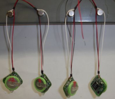
We followed our ten-step silicone coating procedure for four A3013As. At step nine, we discovered no cavities, but we did fill in a few places around the rim of the battery where the coating was thin. By step ten the transmitters looked as you see them above. After that, we clipped off the protruding drops on the bottom corners. Three transmitters were fully-functional. The fourth was not.
We peeled the silicone off the bottom of the broken transmitter, removed the battery, and peeled the silicone off the top as well. Peeling off the silicone works only if you allow each coat to cure thoroughly. With properly-dried silicone, it takes only five minutes to remove the coating. This means that our transmitters can be recycled once their batteries are exhausted.
The battery on our damaged transmitter was drained. The logic chip was drawing excessive current. We did short pin thirteen on the logic chip to the positive battery terminal when we were putting the battery in place. But the transmitter worked afterwards, so we assumed everything was fine. The positive battery terminal is close to pin thirteen and twelve. We must take care to avoid shorting them with solder when we install the battery.
[14-JUN-07] We shipped six transmitters coated using Process I to ION in London by DHL Express. Dr. Walker et al. implanted one in a rat. He obtained reliable reception at ranges up to 50 cm for the first day. At ranges greater than 50 cm, he observed 50% message loss when the rat reached up and touched the metal lit of its cage. The waveforms Dr. Walker et al. observed on channel X were consistent with anesthesias and then waking. We were all delighted.
The next day, the transmitter was dead. Dr. Walker et al. removed the transmitter and measured its battery voltage to be 1.4 V. He placed another transmitter in salt water. The next day it was dead, with battery voltage 1.2 V. Meanwhile, in Boston, we placed a transmitter coated in with Process I in salt water. It operated continuously for two weeks. We suspected that low-pressure in the aircraft cargo hold might have caused the air bubble under the battery to expand, and so burst the encapsulation. Dr. Walker observed cracks in the coating around the battery rim, where the coating is thin.
Dr. Walker coated another transmitter twice with silicone. He placed it in salt water. The next day, it was still transmitting well, but its analog inputs were shorted together internally. This happened with a second transmitter also. We suspect that salt water is penetrating between the wires to the circuit board.
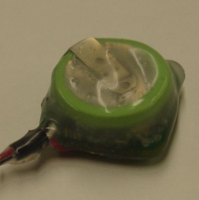
Meanwhile, in Boston, our transmitter in salt-water detects mains hum when we take it out and wave it around. We suspect that whatever passage exists for salt water to penetrate between the wires was opened up by air bubbles expanding and bursting through the silicone. We set up a vacuum pump and bell jar. First, we took a close-up picture of the transmitter we had been keeping in salt-water. The photograph is below. There is rust on the corner of the positive battery terminal. There is a hole in the coating at that point. When we pressed on the coating, we saw water moving around beneath.
Despite the rust, the transmitter is still working. We placed it in our vacuum chamber, along with our video camera. Next to the transmitter we placed the finger from a latex glove, tied off at the end. This finger expands as we evacuate the air, and so acts as a primitive pressure meter. We evacuated the chamber and filled it up again. We see the transmitter swelling up like a small balloon. We expect the silicone coating to burst, but it does not. We can, however, imagine the coating bursting along any line of weakness. To download the video, click here.
We put the transmitter back in salt water. Two days later, it is still transmitting. We record its input noise and average voltage every six hours. After the weekend, we take the transmitter out of salt water and test the X input to see if it will pick up mains hum. It does not. The is a voltage applied across the X+ and X− lines. This voltage is −0.9 V when open-circuit, and 0.09 v when loaded by 100 kΩ. These observations that the red wire is connected to 0 V through a 1 MΩ resistor. When we connect X to an external 3-V battery, we get small 1-mV changes in the measured X voltage. This suggests that the X signal inside the circuit has been connected to ground through a resistor.
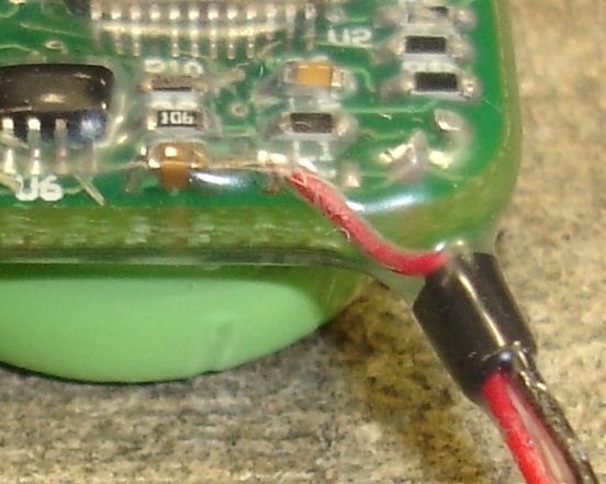
When we examine C7, the 100 nF capacitor in series with X+, we see corrosion on the X+ side of the capacitor, which you can just about see in the photograph above. Also, the silicone coating appears to have come away from the circuit board in a 3 mm × 3 mm area around the point where the red X+ wire is soldered in place. There appears to be a small space between the insulation of the red wire and the silicone around the wire. We conclude that these cavities were created by the expansion of trapped air when we placed the transmitter in our vacuum chamber. Afterwards, salt water seeped in through the cavities and shorted the analog input to ground. This penetration of salt water took anything from one to four days.
[29-JUN-07] We now propose a coating process that we hope will be proof against vacuum, as well as more rugged. In Process II, we make use of silicone bathroom caulk. We find that this caulk, if applied directly to our 10-MΩ analog inputs, causes a temporary disturbance of the circuit behavior while the caulk is wet. But the value of the caulk is that it occupies the space under the battery, where we previously had an air bubble. So we coat the top surface of the transmitter twice with silicone dispersion. We put a large dollop of caulk on the coated top surface and push the battery down onto the caulk, as shown here.
We coat the bottom side with silicone dispersion, then we cut off the programming extension and dip the transmitter in dispersion. We allow the transmitter to hang for ten minutes in our vacuum chamber, as shown here.
In the vacuum, bubbles appear in the dispersion all over the transmitter, and around the base of the wires. After ten minutes, most of these bubbles have burst. We release the vacuum, and all the remaining bubbles collaps. We put some dispersion in a petri dish and placed the dish in the vacuum chamber. A few small bubbles formed at the bottom of the dish, but none of them burst. We conclude that the bubbles in the dispersion around the transmitter contained air drawn out of the transmitter.
Here is Process II, which we hope will be vacuum-resistant. The resulting transmitter looks identical to one coated with Process I.
We placed a glass jar and a wide-mouthed plastic juice bottle in the vacuum chamber. In each container we placed a latex glove finger tied at the end, with a little air in it. We screwed the metal lid of the jar and the plastic lid of the bottle on tightly. We evacuated the chamber. After three hours, the latex finger in the glass jar was partially-inflated. The finger in the plastic bottle was unchanged, although the plastic bottle itself was bulging outwards. We released the vacuum. When we removed the char lid, it popped up as the vacuum inside was released. The finger collapsed. When we removed the bottle top, we heard no rush of air, and the finger inside remained unchanged.
We conclude that the wide-mouthed juice bottle is air-tight enough to hold atmospheric pressure in a low-pressure cargo hold for a flight across the Atlantic. We coated four transmitters using Process II and put them in the bottle for transport to London. We delivered the transmitters on 29-JUN-07. The fate of these four transmitters, as reported by ION on 14-AUG-07, was as follows.
For a look at the data taken by transmitter A, see here. It's still not clear if Process II was proof against salt-water. The first transmitter may have failed because of an assembly error, such as a poorly-soldered in or a loose piece of metal between pins. The paraffin and secondary silicone coating we think unlikely to improve the water-proofing of the transmitters, because salt-water penetration now takes place between the wires, not through the main body of the coating.
[15-AUG-07] On 07-AUG-07, after near-continuous operation since 11-MAY-07, this same transmitter (serial number 011) failed. We measured its battery voltage one day later and found it to be 1.4 V. We removed the silicone coating. We confirmed that the end of the red wire was corroded. We examined the heat shrink and found that there was no silicone inside the heat shrink, so that there were longitudinal cavities around the wires within the heat shrink. The silicone had become detached from the wires on the far side of the heat shrink, and vacuum had opened cavities on the near side. We stripped the end of the red wire of its insulation and found the stranded copper within to be shiny. We conclude that water penetrated through the heat shrink and into the transmitter. We later recovered the poorly-coated transmitters from ION and found some obvious holes in their coatings, as we describe here. Although we at first believed one of the four transmitters was damaged, we later found it to be fully recovered. Today, all four are ready to be coated again.
[16-AUG-07] Here is Process III:
This process does not use a vacuum chamber. Instead, it attempts to fill cavities with caulk directly. We fill the heat shrink that binds the wires together at their base with caulk before we heat it. We fill the gap beneath the battery with caulk. We coat the outside of the transmitter with caulk, which makes sure the battery terminal is well-covered. The resulting transmitter is not as attractive as those made with the earlier processes, but the process itself is simple and easy, and the result appears to be rugged.
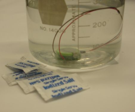
We coated a transmitter with Process III. The figure below shows a picture of the top side with wires. We placed the transmitter in a vacuum for one hour, then left to soak in salt-water. The figure below shows the transmitter in its beaker of 1% saline solution, and the packets of salt we used to make up the solution. Each packet contains 0.7 g of salt. We used four packets in 280 ml of water.
We turned on the transmitter and began monitoring its transmissions. We obtained what we believed were signs of water leaking along the wires, as you can see here . We ripped off the coating, but could see no sign of water along the wires. When we looked at the data more closely, we saw that we had two transmitters with ID number 8 turned on at the same time. We received 1024 messages in one second. We removed removed the transmitter battery and repeated Process III, except we did not have the benefit of the programming extension while applying the silicone caulk, which made the process messy and difficult. We hung the transmitter up to cure.
[20-AUG-07] Our transmitter is once again coated with Process III. We inspected it and found no holes in the coating. We placed it in our vacuum chamber for one hour. We placed the transmitter in saltwater, agitated the wires, and left it overnight.
[21-AUG-07] We received a noisy signal from the transmitter with the leads open-circuit in air, but a quiet signal with the leads shorted together. For raw data of noisy signal see here. We inspected the transmitter and found two holes in the coating on the bottom side. Both appear to have been formed by bursting bubbles during the vacuum exposure. Removed coating, now see mains hum.
[20-AUG-07] Here is Process IV:
This process is less messy because we do not cover the outer surfaces of the transmitter with caulk. Once again, we make sure that the space within the heat shrink at the base of the wires is filled with caulk, and the space beneath the battery also. We dip the transmitter five times in dispersion in the hope that this will cover the battery terminal with enough silicone to keep it waterproof. The coated transmitter looks just like those made by Process I.
We have a transmitter coated with Process IV. We placed it in our vacuum chamber for one hour. We found a burst air-bubble on the top side of the battery. We put a drop of silicone dispersion on the battery and waited 6 hours. We inspected the transmitter and found no holes. We put it in saltwater, agitated the wires, and left it over-night.
[21-AUG-07] We received a full-range repetitive oscillation even with the X leads soldered together. For the raw data, see here. Message transmission was reliable. We removed the silicone and cleaned with methanol. We obtained the same oscillation. We removed the battery and cleaned again. We obtained a normal 60-Hz mains hum. But current consumption was 60 μA when asleep and 120 μA when active. We placed the transmitter in silicone-eater.
[10-SEP-07] Here is Encapsulation Process V.
The purpose of Process V is to make sure that there are no air bubbles within the silicone coating. We chill the dispersion to reduce the number of bubbles forming in the fluid by boiling. In our previous efforts to fill the space beneath the battery with silicone dispersion, we injected the dispersion into the gap. Here, vacuum sucks the air out, and the dispersion rushes in.
[13-SEP-07] One transmitter had a hole in its dispersion beneath the battery, even after the fifth coat. We removed the coating from this transmitter. The other transmitter had the space under its battery filled in by dispersion after the first coating in a vacuum. We coated this transmitter four more times, placed it in salt-water and agitated its wires. After three days, it is operating perfectly. We placed it in a vacuum for half an hour, dropped it in salt-water again and agitated its wires. After half an hour, it is working perfectly. We are not convinced that the earlier failure of our transmitter was water-related. We took another transmitter and started coating it with Process IV. Today we applied the third coat of dispersion.
[17-SEP-07] Transmitter working perfectly in the morning. Agitated the wires. At 2:40 pm, we saved 1 second of raw data. The average value of the transmitter signal was 43160 counts, with standard deviation 85 counts. The average value is 1.8 V and the maximum value is the battery voltage, so the battery voltage is 2.73 V today. There is not sign of the battery being drained. [18-SEP-07] Average value 43190 counts, standard deviation 83. [19-SEP-07] Still going, but now getting some low-frequency waves in analog signal. The wires are still wrapped together, but their tinned surfaces are dull and dark gray. We soldered the wires together and the low-frequency waves vanished. Average value is now 4381, with standard deviation 79. [24-SEP-07] Average 42631, standard deviation 76.
[19-SEP-07] Coat number five is cured. We placed the transmitter in vacuum for an hour. We observed a cavity in the coating before and after the vacuum. We filled this cavity with silicone and allowed to cure for four hours. We placed the transmitter in saltwater after agitating the wires. The average signal is 44900 counts with standard deviation 130. These values imply a battery voltage of 2.6 V and input noise of 18 μV.
[20-SEP-07] Once again, we have full-range repetitive oscillation, even with the X leads soldered together. Radio-frequency transmission is reliable, but the analog inputs are corrupted. Turned off the transmitter and left it in the salt-water.
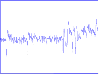
[25-SEP-07] We monitored X over-night, and obtained a graph of the average and standard deviation of X with time, as shown here and described here. Detail of one of the spikes we saw in X is here. Apart from a few spikes of around 100 μV, the transmitter appears to be working perfectly. [26-SEP-07] Average value now 43026, standard deviation 93, 511 out of 512 messages received.
[28-SEP-07] Standard deviation has jumped up to around 200, but transmission is still reliable and average value is around 43000.
[29-SEP-07] The transmitter is beginning to fail. Average value is 46168, standard deviation 215, received only 122 messages out of 512 (data). [30-SEP-07] Transmitter has failed. Large, oscillating analog input signal. Receiving 462 out of 512 messages. Average value is 35169, standard deviation 28988 (data). See the same thing next day.
[01-OCT-07] We removed the wires and stripped them to determine the color of the copper strands at either end. The strands of the black and red wires were almost black from the far end to within 10 mm of the transmitter, where their color changed to dull brown. The strands in the white wire were dull at the far end and shiny at the transmitter end. Removed silicone coating. Battery voltage is 2.6V. Traces of white powder on legs of U3 (see schematic), 5 mm from X− input (black wire).
Cannot turn on transmitter. Removed coating and inspected the electronics. Removed battery, voltage is 2.7V. We see traces of white powder around the base of the red wire and around the base of the positive battery terminal. These two deposits of white powder are separated by 16 mm. The copper strands inside the red and white wires are shiny. The copper strands in the black wire are dark and dull all the way along the 150-mm length of the wire. We found the black insulation hard to strip off the copper strands, as if the two were adhering to one another. We looked at the strands at the base and the far end of the black wire to see if they were more corroded at one end than the other. We could see no significant difference in the color of the wires at either end.
[07-NOV-07] We received four transmitters back from UCL. We inspected the transmitter marked "4" with a loop. We found no holes in the coating, but we did find rat hairs. We put on some latex gloves. We removed the silicone from the bottom side of the one marked "4". We cut the wires off and tried to strip the ends that had been closest to the transmitter. The PVC was brittle. The wires inside were stiff. We lost some of the end pieces, but managed to expose wire that was no more than 10 mm from the transmitter. The figure below shows the three wires and the bottom of the transmitter.
We removed the coatings from the remaining three transmitters and stripped the bases of their wires. None were as severely corroded as the first one we tried. All four black wires were heavily tarnished. The black wire is the one that UCL stripped bare for some distance and used as a ground potential. Two red wires were heavily tarnished, but two were only lightly tarnished. The red wire is the one UCL soldered to their EEG electrode. One of the white wires was heavily tarnished, one was lightly tarnished only at the exposed end, one was tarnished only for 0.5 mm at the exposed end, and the last was not tarnished at all.
[05-NOV-07] One way for water to penetrate a wire is by entering the exposed tip of a stranded wire and creeping along between the wires by capillary_action. A cable-designer we spoke to at Champion Cable said that solid-core wires did not suffer from capillary action because there were no empty spaces within the insulator. Stranded wire, on the other hand, can have small gaps between the strands, depending upon how hard the strands are twisted together and compressed.
Our observations of water penetration are so far consistent with capillary action being the only means by which water penetrates a wire. Our PVC-insulated wires have stranded, bare copper conductors. The conductors are always more heavily tarnished near the exposed end. Our teflon-insulated wires have stranded copper conductors also, but these conductors are tinned by the manufacturer, and the exposed ends of the conductors, although exposed directly to the saltwater, showed tarnishing only where the bare copper was exposed. Even though we saw no tarnishing of our stranded teflon-insulated wires, saltwater may still have crept along them by capillary action.
When we apply solder to the bare, twisted strands of our 0.58-mm diameter wire, we heat the wire at one point with our soldering iron, and apply solder to the hot copper strands. The solder melts and propagates along the the wire in either direction. If we heat the wire farther down with another iron, the solder travels all the way along the wire, in the spaces between the strands and along the outside of the strands, until it passes the second iron and reaches a point where the copper wires are no longer hot enough to keep the solder molten. If we heat the copper wires near the edge of the PVC insulation, and later strip the insulation away, we find the solder has travelled several millimeters within the stranded conductor, but not along its outer surface. There are always gaps between the strands, but there is no gap between the strands and their PVC insulation.
We believe that the movement of solder along an insulated wire as proof that capillary action will draw a liquid into the wire and along to the other end. We will now attempt to use our observations of solder wicking in stranded copper to estimate the speed of water transport along a stranded wire.
In our experience, the speed with which solder moves along hot stranded copper wire in the presence of flux is of order 1 mm/s when it is 5 mm from the soldering iron. The force drawing a fluid along a capillary is generated by the fluid's surface tension, σ. The surface tension of molten solder is ≈450 N, while that of water is 70 N. The contact angle, θ, between solder and copper in the presence of flux is ≈20°, while that of water and copper is ≈ 60°. The force, Fc, drawing fluid along a capillary is given by:
Fc = Aσcosθ,Where A is a dimensionless constant of the capillary cross-section. This force is balanced by the forces resisting movement along the capillary. If we assume the capillary is horizontal, and the fluid is moving slowly, we can ignore gravitational forces and fluid inertia. What is the force that resists the movement of the fluid along the capillary. Suppose we assume that the largest resistive force is skin friction between the fluid and the capillary surfaces.
Fs = Bγvl,Where Fs is the friction force, B is a dimensionless constant of the capillary cross-section, γ is the viscosity of the fluid, l is the length of the capillary so far occupied by the fluid, and v is the velocity of the fluid along the capillary. The viscosity of molten solder is ≈ 0.002 Pa-s. That of water is 0.001 Pa-s.
When we set the two forces into balance, we have:
v = Cσcosθ / γl,Where C = A/B, a dimensionless constant of the capillary cross-section. Using solder as our example, we conclude that C ≈ 2×10-11. Using this value of C, we obtain the following equation for v in terms of l for water travelling along the same stranded wire.
v = 1/l,Where the units of v are mm/s and those of l are mm. By integrating, we obtain l in terms of time, t.
l = √(2t),Where l is in millimeters and t is in seconds. This relationship predicts that it will take water three hours to travel along one of the 150-mm stranded leads we have been using for our X inputs, at which point the water will be moving at ≈10 μm/s. We have observed failure of the transmitters at anything from a few hours to two weeks after implanting.
[07-NOV-07] We conduct an experiment at home. We prepared a length 1-mm diameter PVC-insulated stranded-conductor wire. The wire had 10 mm of stripped wire at either end, and 40 mm of insulated wire in between. We filled a syringe with vinegar, put one end of the wire in the tip of the syringe, laid the syringe on the table, and placed the other end of the wire in a pinch of baking soda. We started a stopwatch and studied the baking soda through a loop. The surface tension and contact angle of vinegar are almost identical to those of water and saltwater. But vinegar creates bubble with baking soda, while saltwater and water do not.
At time 130 s, we observed bubbling in the baking soda. We prepared a 160-mm length of insulated wire and repeated the experiment, this time with bubbling bath color pills ground into powder as our vinegar-detector on the other end. We expected the vinegar to take half an hour to get through the longer wire, after my Fs calculations. But my wife went and looked after 400 s and saw discoloration in the powder as well as bubbling.
We sprinkled powder along the length of the insulation, to see if the vinegar was passing outside the wire. There was no sign of vinegar on the outside of the insulation.
Our results prove that vinegar travels quickly along stranded conductors. Our observations contradict our assumption that the largest force resisting the movement of water in the wire is skin friction, Fc. If it takes 130 s for water to pass through 40 mm of wire, our skin friction model predicts it will take water 16 × 130 s = 35 min to pass through 160 mm of wire. But the water took less than 6.5 min in our experiment.
[08-NOV-07] We set up the apparatus below to measure the rate of capillary transport along various wires.
We filled the petri dish with water at 1:00 pm and started our stop watch. We expected to see transport to the ends of the powder. We waited for an hour. Nothing happened.
At 2:00 pm we added hydro-chloric acid (HCL) to the water until it tasted as acidic vinegar. At 2:08 pm, we saw water affecting the powder at the end of the 40-mm white, teflon, stranded wire. Water continued to seep out of this wire thereafter.
At 2:40 pm, no other wire had shown signs of water. We filled a syring and placed a white, teflon, stranded wire in the end. In a few minutes, we saw signs of water. We tried telephone wire. We saw water in a few minutes. We tried telephone wire again. We saw no sign of water penetration after an hour. We tried once more with a third telephone wire at 4:10 pm. At 4:30 pm there was still no sign of transport.
At 2:45 pm, we placed a yellow, stranded, PVC-insulated telephone wire in the petri dish. We left the lab from 3:00 pm until 4:10 pm. When we returned, we found signs of water at the end of the 1.0 mm black wire and the yellow telephone wire.
We left the apparatus to sit overnight. It appears that transport through wires is dependent upon the exact preparation of the wire ends, independent of the relative height of the wire ends, and may be affected by the acidity of the fluid. So far, none of the solid-conductor wires have transported water.
[09-NOV-07] The telephone wire we left in a syringe is now conducting water. Of the wires in the petri dish, only the three that were conducting water yesterday are conducting water today. We moved the apparatus to a bench and will leave it over the weekend.
[13-NOV-07] After four days, the dish of acidic water has evaporated, all un-tinned copper wires in the dish have disappeared, and there is blue-green copper oxide residue in the bottom of the dish. None of the solid-conductor wires show signs of capillary actions. Nor do the 130-mm stranded wires or the 80-mm stranded wire. The 40-mm stranded wire, however, has conducted water out of the petri dish and into its pile of powder. This proves that the stranded wire we used for our first twenty A3013A transmitters is capable of conducting acidic water by capillary action.
Another way for water to penetrate a wire is by passing through the insulation. Our contact at Champion Cable confirmed our suspicion that PVC is not water-proof over a period of weeks in water. Teflon, on the other hand, is more resistant to water. Water may indeed be penetrating our PVC insulation, but such penetration cannot alone explain our observations. If penetration through the insulation were the only way in which the PVC wires were leaking, we would see equal tarnishing along the entire length of our immersed samples. But we see less tarnishing towards their centers.
Only by delivering water to the transmitter circuit could the wires disturb the circuit operation and eventually drain its battery. If penetration of saltwater through the insulation were the only means of penetration, the water introduced into the wire would have no means of moving along the wire and into the transmitter.
The transmitter failures we have observed recently in saltwater are consistent with the transport of water along the wires by capillary action, and subsequent accumulation of water within the transmitter. The speed with which water can travel along the wires is, we believe, a function of the amount of space between the wires, but also the exact nature of the tinning we apply to the wire end. The tinning might be minimal, leaving bare copper exposed around the insulation, or the tinning might have penetrated into the wire by its own capillary action, and so sealed almost all the spaces between the wires before water can enter in. Some transmitters fail after a few hours in saltwater. Such failure is consistent with water moving freely by capillary action along the stranded wires. Other transmitters endure for two weeks. Such endurance may be the result of complete blocking of the wire ends by tinning, so that water was forced to enter the wires by passing through the PVC insulation. We never paid particular attention to the manner in which we tinned the ends of the wires, so we cannot say if the longer-lived transmitters were tinned any differently from the short-lived transmitters.
When we examined wires on transmitters returned from UCL (see above), we found that some were tarnished and others were not. On one transmitter, the black wire was heavily tarnished at the base, while the red wire was only lightly tarnished and the white wire was not tarnished at all. The black and red wires were exposed to the same environment, and the only significant difference between them was the preparation of their far ends. One was stripped to act as an earth wire, the other was soldered to an electrode. The length of the wire cannot be leaking. It was the tip of the wire that leaked.
We demonstrated capillary transport of water on our dining room table and in our lab. We observed transport along a 16-cm stranded wire in under six minutes. But we see no clear relationship between the type of stranded wire, its length, and the time it takes for the wire to conduct water from one end to the other. We suspect that the capillary action depends upon the manner in which we prepare the wire end. Grease, solder, trapped air, and orientation may all enable or inhibit capillary action. We never observed or saw signs of capillary action along a solid-conductor wire.
We conclude that capillary action has been drawing water into our transmitters through the tips of their wires. The water passes along the spaces between the stranded conductors. The copper strands corrode, and PVC insulation degrades. The water transported into the circuit disturbs its operation at first, and eventually drains its battery.
Water-proof wires must either be solid-conductor, in which there are no space for the water to occupy, or we must seal the ends of the stranded wire by tinning them or coating them with silicone. Water-proof wires must use insulation that does not degrade in saltwater. Teflon is a water-resistant material, but our PVC insulation is not.
[02-NOV-07] Here is our encapsulation process Process VI. The result is a transmitter with four coats of silicone, no bubbles in the coat, no air pocket beneath the battery, and an antenna sealed by silicone at the end. We also note that the final step in the process exposes the main body of the coating to a vacuum.
We examined the cross-section of the stranded wires of Transmitter 8 with a loop, and found that the strands were pressed together into a matrix with no visible spaces between them. But we are confident that such spaces exist. We did not tin the ends of the black and red stranded wires. We want to encourage saltwater to penetrate the stranded wires by capillary action. Tinning might fill the gaps between the strands and so keep the water out. Instead we stripped 10 mm off the end of each and wrapped them together. With the inputs shorted, the X input should be zero volts, or roughly 43000 ADC counts. We confirmed this was indeed the case before we placed the transmitter in saltwater.
We soldered together the ends of the silver wires of Transmitter 10. We are confident that water cannot travel within the solid silver wire's teflon insulation, regardless of whether or not we tin the wire ends. We found that if we immerse the thin teflon insulation in solder, it burns off and we can solder the wires together. Burning off the insulation saves us having to scrape it off with a scalpel. We confirmed that the shorted X input read roughly 43000 ADC counts.
Although we sealed both antenna wires with silicone, we find that the silicone seal, the heat shrink, and the tip of the antenna wire tend to shift up and down the X wires. The silicone does not adhere well to the teflon insulation. Water may be able to penetrate into the tip of the antenna wire and so enter the circuit.
[03-NOV-07] We placed both the above transmitters in water on. The stranded-wire transmitter was turned off. The silver-wire transmitter was turned on. Both showed stable DC values near 43000. Transmitter 8 noise was ≈90 counts, Transmitter 10 noise was ≈180.
[05-NOV-07] The silver-wire transmitter shows no change. Message reception is 100%. The stranded-wire transmitter shows slowly-varying DC voltage. Its DC voltage was previously stable.
[06-NOV-07] We now have both transmitters turned on and running in saltwater. Wires and transmitters are all immersed. We get the following one-second reading from the two of them.
Below is a table of the performance of each transmitter over the next few days.
| Time | ID=8 Received | ID=8 Average | ID=8 Noise | ID=10 Received | ID=10 Average | ID=10 Noise |
|---|---|---|---|---|---|---|
| Freshly coated | 512 | ≈43000 | 90 | 512 | ≈43000 | 180 |
| 4.0 days in saltwater | 505 | 4400 | 400 | 512 | 45700 | 70 |
| 5.0 days in saltwater | 512 | 3400 | 70 | 512 | 44300 | 90 |
| 5.5 days in saltwater | 512 | 6200 | 313 | 511 | 44700 | 80 |
| 6 days in saltwater | 510 | 5170 | 49 | 510 | 55600 | 110 |
| Stripped, cleaned, leads removed | 497 | 44400 | 122 | 512 | 44600 | 210 |
Transmitter 8, with stranded wires, is failing on day 4. It's average and noise are both wrong for a transmitter with its input wires shorted together. When we remove it from the water and touch its leads, we see 60 Hz hum with its negative swings cut off. With the X leads open circuit, we measure a voltage of around −1.6 V between X+ and X−. Our discussion of capillary action above suggests that water has travelled along the stranded wires by capillary action, entered the transmitter circuit, and connected X+ to 0 V with a saltwater film.
Transmitter 10 may or may not be failing on day 4. Transmission is reliable and the input noise is low. But the average value of the input suggests that the battery voltage has dropped from 2.7 V to 2.5 Vm, and the noise was higher before we put the transmitter in water. It may be that water has penetrated along the antenna wire and is draining the battery. We know that water cannot have penetrated along the silver wires, because such water would immediately connect the X inputs to other active signals, and cause noise.
[08-NOV-07] The DC value of Transmitter 10's input has jumped up. After our experiments at home with capillary action (see above), we are convinced that any stranded wire is a rapid and efficient conductor of saltwater into the transmitters, and we decide to abort the experiment.
We removed the coating from Transmitter 8 (stranded wires). The coating was tough and resilient. Once we had cut through it, however, we were able to peel it off easily. We washed the transmitter with ethanol. The black and red wires broke off. They were brittle at the base. There is a green mark (copper oxide) at the end of the tip of the white wire. Battery voltage is 2.7 V. Transmitted data is back to normal (see table above), although reception is only 97%.
We stripped and cleaned Transmitter 10. Battery voltage was 2.6 V. The input was noisy, with DC level shifting. We cleaned repeatedly and obtained the result in the table above. We soldered a new antenna wire in place and the battery voltage dropped to zero. We attempted to repair the transmitter, but it appears the logic chip is broken.
[09-NOV-07] We resolved to test Process VI again, this time with wires we can be sure are water-proof. We use a solid-core, teflon-insulated copper wire for the antenna, and teflon-insulated silver wire for the X inputs. The antenna conductor is 0.44 mm in diameter, and the silver conductor is 0.2 mm in diameter. The antenna conductor is stiff enough that we can hang the transmitter by a bend in the wire.
[15-NOV-07] Transmitter 8 now has five coats, but is behaving strangely. It's DC voltage is drifting up and down, and reception is poor. Today we received 461 out of 512 messages, with average value 43568 and noise 98. But we often get noise 400 counts. We put the transmitter in water anyway.
[16-NOV-07] Transmitter 8's DC drift problems have grown worse. We took it out of the water, tore of the silicone, and cleaned it with alcohol. The DC value stops drifting. Was there water trapped under the silicone coating?
[17-NOV-07] We measured the performance of various diameter solid wires as antennas, as you can see here. A 0.2-mm silver wire was just as effective as 0.44-mm copper wire. Now we try a 250-um diameter, tinned, solid copper wire with blue PVC insulation for the antenna. This wire is one designed for the old circuit prototyping method known as wire-wrap. With the blue antenna, we receive 512 messages out of 512. We stretch some of our thinnest heat shrink, which narrows its diameter and thins its walls at the same time. We use this to bind the antenna at the base and tip.
Our hope was that this transmitter would be entirely water-proof, but we were to be disappointed.
| Date | Received Messages (s−1) |
Average (counts) |
Standard Deviation (counts) |
Comment |
|---|---|---|---|---|
| 16-NOV-07 | 511 | 43638.3 | 80.7 | uncoated |
| 16-NOV-07 | 512 | 44699.4 | 125.8 | one coat |
| 19-NOV-07 | 512 | 43934.7 | 80.7 | 5 coats + 1 day |
| 20-NOV-07 | 511 | 43926.9 | 87.4 | 5 coats + 2 days |
| 21-NOV-07 | 512 | 43913.7 | 78.0 | 5 coats + 3 days |
| 21-NOV-07 | 500 | 43820.2 | 84.5 | dropped in water |
| 21-NOV-07 | 500 | 43803.4 | 78.3 | 1 min water |
| 21-NOV-07 | 509 | 43820.2 | 82.4 | 5 min water |
| 21-NOV-07 | 506 | 43881.2 | 86.8 | 30 min water |
| 21-NOV-07 | 505 | 43806.4 | 83.0 | 2 hr in water |
| 22-NOV-07 | 485 | 42753.2 | 22.8 | 24 hr in water |
| 22-NOV-07 | 496 | 43705.7 | 171.6 | 25 hr in water |
| 22-NOV-07 | 476 | 41506.3 | 130.6 | 27 hr in water |
| 22-NOV-07 | 468 | 43190.7 | 652.9 | 36 hr in water |
| 23-NOV-07 | 471 | 33934.1 | 31313.9 | 2 days in water |
| 26-NOV-07 | 470 | 39390.4 | 237.6 | 5 days in water |
| 26-NOV-07 | 506 | 45637.8 | 358.4 | out of water, next to antenna |
| 27-NOV-07 | 512 | 37314.8 | 75.6 | cleaned, 1m from antenna |
We subjected the first coat of silicone to vacuum for five minutes and observed the usual bubbles. The coating dries quickly in vacuum. Already the silicone was stiff. We coated again immediately and put the transmitter back in the vacuum for five minutes. We dipped a third time and hung the transmitter to cure. We observed several large bubbles caught beneath the first and second coats. We punctured them with a probe. It could be that the vacuum is not necessary, and even causes problems. All leaks up until now can be explained in one of two ways: cracks in the coating caused by the large bubble under the battery expanding in a vacuum, or water entering through the stranded wires. It may be that we don't need to subject the first coat to vacuum, so long as we have filled the gab beneath the battery with silicone caulk.
[19-NOV-07] After the first coating, the DC value of the input voltage jumped up from 43600 to 44700, and noise jumps from 80 to 126. We later observe holes in the coating, and we add some silicone caulk to fill in the gap around the edge of the battery. We coat twice more. By the end of the weekend, the transmitter seems to be behaving itself. We will leave it for another couple days to establish its dry performance before putting it in water.
[21-NOV-07] Place in water, antenna horizontal, completely immersed. Lose some messages, otherwise everything looks good until the evening, when we observe frequent 1-Hz fluctuations in X, which we will call rumble. The rumble combines with white noise to generate 200 counts of noise. We do not record data.
[22-NOV-07] Noise has dropped to 23 counts. The DC value has dropped slightly to 43000. The noise looks normal, and has a white spectrum, but it is a factor of three smaller than we are used to. An hour later, we look again, and find the noise has jumped back up again to 171 counts. The rumble has returned, and is accompanied by an increase in white noise.
Later the same day, we get even bigger rumble, raw data here.
[23-NOV-07] The X input is oscillating between 0 and 65535. We have seen this behavior before, and we associate it with failure by water penetration. Despite the fact that we coated five times, filled the space under the battery with silicone, and used solid-conductor wires for all three leads, water still penetrated the transmitter. Nevertheless, we have a good record of the stages of failure, and we are certain that the transmitter was stable before we placed it in water.
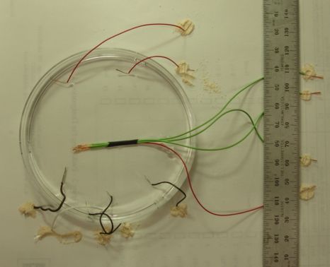
[26-NOV-07] For the past year, we have been using flexible, PVC-insulated wires we bought from McMaster-Carr. The black 0.58 mm (0.023") wire is part number 7071K131. After observing corrosion these wires on 01-OCT-07, we resolved to test wires with other forms of insulation. On 13-OCT-07 we placed two 150-mm samples each of four types of wire in saltwater. On 02-NOV-07 we removed the wires, stripped their ends, cut them in half, and stripped the newly-exposed ends. The table below identifies each type of wire and the condition of the conductors at the ends exposed to saltwater and at the center of each sample.
| Outer Diameter (mm) | Insulation | Conductor | Tip Condition | Center Condition |
|---|---|---|---|---|
| 0.58 | PVC | Stranded bare copper | blackened and dull | brown and dull |
| 0.81 | Teflon | Stranded tinned copper | tarnished at exposed tip | untarnished |
| 0.81 | Teflon | Solid tinned copper | tarnished at exposed tip | untarnished |
| 0.60 | Paint | Solid copper | tarnished to 5 mm from tip | untarnished |
| 0.28 | Teflon | Solid silver | not tested | not tested |
We also have teflon-insulated silver wire, which we did not include in the above test. The silver wire is solid-core and 0.20 mm in diameter.

The PVC-insulated wires were most heavily tarnished at the ends, but they were visibly tarnished all the way through. We observed on 01-OCT-07 that all our PVC wires were more heavily tarnished at the ends that were exposed to water. The antenna wires were less tarnished at the exposed ends, but the ends of the antenna are enclosed in heat shrink and sealed with silicone.
The X input no longer oscillates. We see rumble and noise (raw data here. We remove the transmitter from saltwater, clean it with water and alcohol, blow it try with nitrogen, and put the cold transmitter next to our receiving antenna. We receive 506 messages in a second. The rumble is still present. We disconnect the silver wires to see if we can detect mains hum. We see hum superimposed upon increased noise and rumble, raw data here.
We inspect the transmitter and see no sign of water inside, nor of openings in the coating. Where the wires pass from the heat shrink to the circuit board, we see space around the wire insulation. Where the silicone coating ends on the teflon wires, the silicone is rough. It does not adhere well to the teflon. The bond between the silicone and the blue PVC wire is better. We pinch off the heat shrink and look at the cross-section of the silicone where it covers the three wires on their way to the circuit board. The silicone is not tight on the wires. The wires have cut space for themselves. We saw no silicone packing the inside of the heat shrink. Our use of vacuum to such silicone into the space within the heat shrink and around the wires did not succeed.
We pull off most of the silicone, but not all of it. Some caulk remains around the analog inputs. The battery voltage is 2.7 V. Still see rumble and noise. Clean with alcohol. Rumble and noise remain. We remove the battery and wires, and place the transmitter in silicone eater.
[27-NOV-07] Clean off Transmitter 8. We brushed it repeatedly yesterday and this morning, while in the silicone eater, and find it completely clear of silicone today. We add an antenna and connect a battery with current monitor. Inactive current is 19 μA. Active current is 83 μA. With X inputs shorted we receive a strong signal with no rumble and noise of 76 counts. With leads soldered to X we see mains hum.
We conclude that water leaked into Transmitter 8 within 24 hours of its immersion in saltwater. The water did no damage to the circuit.
[28-NOV-07] In our experiment with Transmitter 8 ending on 26-NOV-07, we suspect that water penetrated along the outside of the wires, through the open space within the heat shrink, and along the spaces around the wires to the circuit board. Our Process VII is designed to produce a robust seal around the wires where they wires penetrate the silicone coating and emerge from the transmitter.
This process applies six coats of silicone to the transmitter. If we could eliminate bubbles from the silicone, we could omit the final three steps of the process, and make do with only four coats.

We coat Transmitter 7 returned from ION. After Step 1 we find its RF power output of this transmitter is −20 dB below normal (see here for spectrum from Spectrometer Tool, green is normal, red is Transmitter 7, 10 dB per division). Transmitter 7 was one for which we had 10% missing messages when we first constructed it. We use three PVC-insulated, wire-wrap wires for our leads. We coat Transmitter 8, featured in Stages of Failure. We use teflon-insulated silver wire for the X leads and PVC-insulated copper wire for the antenna.
| Date | Received Messages (s−1) |
Average (counts) |
Standard Deviation (counts) |
Comment |
|---|---|---|---|---|
| 27-NOV-07 | 512/506 | 45356/44537 | 89/114 | Step 3, next to antenna |
| 28-NOV-07 | 512/512 | 44459/44208 | 71/81 | Step 4, next to antenna |
| 29-NOV-07 | 512/511 | 44710/45638 | 77/178 | Step 5, next to antenna |
| 30-NOV-07 | 512/512 | 45295/44844 | 78/122 | Step 7, next to antenna |
| 04-DEC-07 | 512/512 | 44867/44828 | 72/127 | Step 10, next to antenna |
| 04-DEC-07 | 480/493 | 44197/45821 | 66/197 | 1 minute in saltwater |
| 04-DEC-07 | 512/486 | 44658/45295 | 71/165 | 1 hr in saltwater |
| 04-DEC-07 | 513/493 | 44656/44953 | 75/167 | 2 hr in saltwater |
| 04-DEC-07 | 512/505 | 44110/44641 | 74/168 | 4 hr in saltwater |
| 05-DEC-07 | 511/499 | 60436/43494 | 60/327 | 18 hr in saltwater |
| 05-DEC-07 | 512/512 | 37898/43712 | 66/512 | removed, cleaned, stripped, refurbished. |
Steps 1 and 2 of Process VII appear affect the X input of Transmitter 8. The average value jumps from 37315 to 44537, which corresponds to a drop in battery voltage from 3.2 V to 2.6 V. We expect this sudden drop in battery voltage in the first few minutes after we solder the battery to the board. The noise rises from 76 to 114. After Step 3, the noise is down to 81, but the next day, after Step 4, the noise is up to 178. We conclude that Transmitter 8's noise varies from 70 to 200 counts from one hour to the next. When we leave the transmitters stationary in air, we see no rumble. When we move the transmitters around, we see plenty of rumble, as shown below.
We see rumble on the inputs even thought the inputs are shorted together. The Transmitter 7 leads are twice as long as the Transmitter 8 leads, and we almost always see more rumble on Transmitter 8.
[30-NOV-07] We found cavities in the coating on the underside of both transmitters. The cavities are along one edge of the logic chip, the same edge on both chips. It is the edge that is uppermost while the transmitter is hanging up to cure. Both transmitters had small tunnels through the coating that were about 0.2 mm in diameter. There were many bubbles trapped in the silicone along this edge, and between the legs of the logic chip. We filled the tunnels with caulk and dipped the transmitters again. Immediately after dipping, the holes are covered by a smooth, flat layer of silicone dispersion. Once the coating is almost cured, the hole in Transmitter 7 appears to be covered and sealed. But the Hole in Transmitter 8 shows as a dent in the coating. We dip both transmitters again, to be sure.
We believe the tunnels arise and persist in the following way. First, an air bubble is trapped beneath the silicone. As the silicone dries, it shrinks. The bubble bursts, leaving a cavity. The next layer of silicone covers the cavity but does not enter it. As the silicone dries, it shrinks. The silicone over the cavity has no backing, and stretches away from the cavity center. It stretches thin and bursts. The frayed edges of the tear fall down into the cavity, closing its opening by about 100 μm. If the cavity entrance starts off at 500 μm, it will take five layers to seal the cavity, and another layer to provide a secure coating over the seal.
The cavities appear to be caused by bubbles of air emerging from beneath the components on the bottom side, in particular the logic chip. These bubbles emerge slowly. They rise up to the top side of the logic chip and become frozen in the curing silicone. If we immerse the transmitter in a vacuum, these bubbles expand and emerge faster. When we remove the transmitter from the vacuum before the silicone dries, the remaining bubble shrink dramatically, so that they are too small to cause cavities. We may be able to eliminate the final three stages of Process VII if we add a vacuum chamber step after the first silicone immersion.
[04-DEC-07] Coating has no cavities. We are careful not to agitate the wires, nor do we put the transmitters in vacuum. We immerse both transmitters in saltwater.
[05-DEC-07] Check transmitters from home in the morning and find they are already failing. Raw data here. The rumble in Transmitter 8 suggests penetration along the X leads, both of which are teflon-coated silver. The jump in the average value of Transmitter 7 suggests water penetration along the antenna wire to the supplies of the RF oscillator, thus draining the battery.
When we get to the lab, we confirm that the transmitters are failing, remove them from saltwater, and wash them in fresh water. We inspect the coating for cavities. We find none. We strip off the coating. When we pull the black tube with compressed silicone off the wires of both transmitters, we have to pull hard. But close inspection reveals that the PVC insulation on the blue wires has been damaged by the heat we used to shrink the black tube. Wash in alcohol, and try them again. Transmitter 7's battery voltage is 2.5 V, but it won't turn on. Resistor R3, which is part of the switch circuit, has been fractured by the trauma of pulling the silicone from the board. We replace R3 and the battery. Transmitter 7 is back to normal. It's average value is lower because the battery is new. Transmitter 8's battery voltage is 2.7 V, and it is back to normal after cleaning, without any repairs.
We observed cavities in the coating even after four layers of silicone. We are convinced that we covered these with the fifth and sixth coats. Both transmitters ran well for a week before we immersed them in saltwater. They both showed early signs of failure within 18 hours of immersion. We conclude that water yet again penetrated along the outside of the lead wires.
Despite the failure of Process VII, we are pleased with the antenna arrangement of Process VII. The reverse loop gave good reception and maintains its shape well.
In Process VIII we carry the transmitter's three external electrical connections through the silicone coating with three rigid pins. By a stroke of good luck, the locations of the three lead connections lie approximately on a 0.1-inch pitch, and we can solder to them a 0.1-inch pitch connector.
This process avoids cavities in the silicone around the logic chip by coating the bottom side with epoxy.
Below is a photograph of Transmitter 8 after Step 2. Note the residual tiny bubbles in the surface of the epoxy. These are bubbles that shrank after we removed the transmitter from the vacuum.

We keep track of the behavior of Transmitter 8 during and after Process 8 in the following table.
| Date | Received Messages (s−1) |
Average (counts) |
Standard Deviation (counts) |
Comment |
|---|---|---|---|---|
| 05-DEC-07 | 512 | 44387 | 118 | Epoxy curing after Step 2 |
| 05-DEC-07 | 495 | 44919 | 146 | Epoxy curing after Step 3 |
| 07-DEC-07 | 508 | 44304 | 160 | Coat curing after Step 7 |
| 10-DEC-07 | 476 | 44677 | 131 | Coat complete, 3 m from receiver. |
| 10-DEC-07 | 512 | 44461 | 167 | Coat complete, next to receiver, X inputs shorted |
| 10-DEC-07 | 509 | 43712 | 288 | 10 s after immersion in saltwater |
| 10-DEC-07 | 489 | 45101 | 646 | 100 s after immersion in saltwater |
| 10-DEC-07 | 480 | 46419 | 273 | 10 min after immersion in saltwater |
| 11-DEC-07 | 485 | 45495 | 808 | 24 hr after immersion in saltwater |
| 11-DEC-07 | 486 | 44553 | 160 | removed briefly, wash and dry |
| 11-DEC-07 | 471 | 45704 | 424 | 28 hr in saltwater |
| 11-DEC-07 | 497 | 45291 | 366 | 34 hr in saltwater |
| 12-DEC-07 | 493 | 45014 | 478 | 50 hr in saltwater |
| 13-DEC-07 | 453 | 44586 | 271 | 72 hr in saltwater |
| 14-DEC-07 | 420 | 44284 | 241 | 96 hr in saltwater |
| 14-DEC-07 | 512 | 41785 | 147 | clean in water jet, place in vacuum for 1 hr, clean in water jet, dry with compressed air, allow to warm up for five minutes. |
| 14-DEC-07 | 480 | 43206 | 115 | drying after experiments |
Step 3 requires some care: if we apply too much epoxy, it drips down from the pins and makes a drop somewhere else on the transmitter. We removed the excess epoxy with a piece of tissue. We added more silicone caulk around the underside of the battery to replace the caulk we had ripped off when we removed Transmitter 8's coating on 05-DEC-07. The result is shown below.

When the transmitter is hanging to cure after Step 4, we see one large bubble remaining beneath the surface of the silicone dispersion. After Step 6, the bubble is well-covered with silicone, and we see no cavities in the coating.
[10-DEC-07] We clip the hardened drop of silicone from the bottom corner of the transmitter. We push back the silicone on the three gold-plated leads. We solder a new antenna to the center lead, cocver the joint in heat shrink, and connect the X leads with a wire link. Connecting the wires appears to increase the X input noise.

Because the metal of all three pins is exposed, the antenna and the X leads will be in contact with one another through the saltwater. The resistance between two 5-mm pins separated by 2.5 mm in our saltwater is of order 1 MΩ. We drop the transmitter into saltwater. Within 10 s we see rumble on the X input, and over the next few minutes we see jumps of order 1 mV. After 10 minutes, the X input has settled to a noise of under 300 counts, and a steady average value.
[11-DEC-07] The jumps in X are back. We recorded an example, as shown above. We took the transmitter out of the water and cleaned it. The jumps were gone. We put the transmitter back in the water and the jumps returned immediately. We conclude that the jumps are caused by conduction between the antenna lead and the X inputs.
[14-DEC-07] We are convinced that Transmitter 8 is water-proof. We clean it off with a strong jet of water, place it in a vacuum for one hour, clean it with the water jet again, dry it in compressed nitrogen. The transmitter is now cold. Its spectrum is shifted up by 5 MHz. Otherwise, the transmitter appears to be functioning well. We remove the X connections and the antenna. We have to scrape oxide off the solder joints. The voltage between the antenna and X+ is zero, which we expect, because X+ passes immediately through a capacitor. But the voltage between X− and the antenna is 0.95 V. We have observed before that the antenna becomes connected to the positive battery supply. This connection is not associated with water damage, but rather to aging of our MAX2624 source of RF power. We would rather there was no DC voltage on the antenna, but in this case the voltage allows us to measure the battery voltage. The X− input is at 1.80 V, so our 0.95 V measurement means the battery voltage is 2.65 V, which shows the battery is still well-charged.
The silicone around the base of the pins is coming apart. The water jet and the compressed air have combined with the soldering iron and some acid flux to force the silicone away from the pin surfaces. We cut the silicone off the pins with a scalpel. The coating around the connector epoxy is loose for about 2 mm from the edge. We used Transmitter 8 in an experiment described here. The experiment destroyed the transmitter, so we are unable to continue our observations of Process VIII.
[07-DEC-07] Ralf Schoepfer of UCL asked if we could move the battery off the A3013 circuit board and put it elsewhere. Moving the battery off the board would distribute the bulk of the transmitter, making it easier to implant in smaller animals. We would also be able to use a smaller battery if we were willing to sacrifice operating life for smaller size. Another advantage of moving the battery off the board is that we could cover both sides of the board with epoxy in the same way we coat the bottom side in Process VIII.
Our Process IX encapsulates the transmitter entirely in epoxy. We prepare the transmitter by connecting thin, solid wires to the X terminals, the antenna, and the battery terminals, as shown below.
The working life of our black EP965 potting epoxy is twenty minutes. We allowed our epoxy to sit for ten minutes. This ten-minute delay increases the viscocity of the epoxy. We applied epoxy to both sides and around the edges with a syring and thin wooden stick. The result is shown below.
We soon observed a drop of epoxy forming on the underside of the transmitter. We removed the drop. Another bulge formed within ten minutes, but not quite a drop. Some components on the underside are now exposed. The top side, however, has a uniform coating. We conclude that we will obtain more reliable results, with less epoxy, if we coat only the top side, and so encapsulate the transmitter in two steps.
[10-DEC-07] The epoxy is dry, smooth, and hard. There is a bulge in the center of the bottom side, and around the bulge, we see sevarl components exposed. In one place there is cavity opening onto the circuit board. We put a drop of fresh epoxy upon this bulging surface, spread the drop around, and placed the transmitter in a vacuum for five minutes to suck the air out of the cavities. The result is a smoth surface with all parts covered.
The wires bend where they emerge from the epoxy. Because they bend, we will not be able to make a water-proof seal around the wires with silicone. Better than wires would be stiff pins.
We decide to coat Transmitter 11 with epoxy. This transmitter works, but gives 10% missing messages. Instead of stripped wires, we use square, gold-plated pins. We apply epoxy to one side and place the transmitter in a vacuum. We see many bubbles emerging from the epoxy and bursting. One such bubbles was 5 mm in diameter. After the bubbles burst, they fill in with epoxy. After ten minutes, we remove the transmitter. The epoxy coating is smooth and compact. We leave it to cure.
[11-DEC-07] We apply epoxy to the second side of Transmitter 11, place in vacuum for ten minutes, and leave to cure. After an hour we notice a bulge in the epoxy on the bottom side. Epoxy has flowed off the top side to the bottom side. We smoothed this bulge out with a wet finger.
[12-DEC-07] Some thin patches remain on the top and bottom sides of Transmitter 11. We apply more epoxy to both sides at the same time, and also to the base of the pins. We leave the transmitter to cure. When the epoxy is almost hard, we coat the transmitter with silicone by immersing it entirely in the dispersion. We hang it in a vacuum for ten minutes, and then to cure. We dip the transmitter again four hours later, but skip the vacuum.
[14-DEC-07] We dip the battery and its pins in dispersion and hang to cure. An hour later, we notice that a sharp point on one of the battery pin solder joints is protruding from the coating. We clip off the point and dip the battery again. The silicone does not flow evenly down the wires that join the transmitter to the battery. The result so far is thin on one side and thick on the other. We used Transmitter 11 in an experiment described here. The experiment destroyed the transmitter.
[15-DEC-07] Process X uses epoxy for cavity-filling, binding the connector pins to the board, and the first layer of water-proofing. Because epoxy fills the cavity between the battery and the printed circuit board, we cannot replace the battery once the tranamitter is encapsulated. Silicone provides the outer coating. The outer coating gives the transmitter a smooth and yielding texture for greater comfort in the animal. It also protects the external lead wires and the identification label. Although Process X is irreversible, it has several benefits that, in our view, outweigh its irreversibility.
Having listed the advantages of Process X, here are the steps of the process itself.

We expect this process to work equally well for a two-channel transmitter. We add a second connector for the Y inputs. The second connector has only two pins.
We do not specify what type of wire to use with Process X. The wire does not penetrate the water-proof coating of the transmitter, so it cannot cause transmitter failure. We do, however, recommend that the antenna wire be 65 mm long (the pins add 10 mm to the effective antenna length) and held to the X leads by a short length of heat shrink. In particular, we recommend the reverse-curve antenna arrangement shown here.
After we encapsulate a transmitter, we will subject it to our quality assurance.
[26-DEC-07] We tested Process X on a transmitter we thought was broken. But when we moved a magnet near it, it turned on. It's ID is 11, but it is not the same Transmitter 11 we used in Process IX. We turn on the transmitter and put it in saltwater.
We complete Step 6 for four other transmitters, as shown here. Two of the transmittes have a white, stranded-core, teflon-insulated antenna. For their X leads, these two have solid silver wires with clear teflon insulation. The other two transmitters have a blue, solid-core, PVC-insulated antenna. Their X leads are the same type of wire, but X+ is red and X− is gray.
While testing the four transmitters before we dipped them in silicone, we found their operating range approximately doubled when we completed the antenna's reverse bend.
[27-DEC-07] We apply the final two coats of silicone. Transmitter 11 is still behaving perfectly in its saltwater.
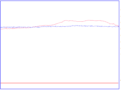
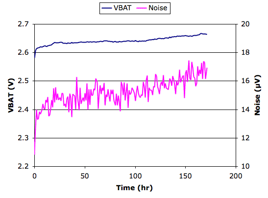
[01-JAN-08] Transmitter 11 still behaving perfectly. Below is a graph of battery voltage and noise that we will update from time to time. Every work day we agitate the transmitter in its satlwater once or twice. We plan to let the transmitter run until its battery expires.
[02-JAN-08] Four transmitters coated with Process X are ready. Their combined volume is 11 ml, or 2.8 ml each. We begin our quality assurance process by placing the transmitters in a vacuum for an hour. Transmitter 7 was non-responsive. The others appear to be okay, although the noise on Transmitter 4 is twice as high as normal.
| Step | ID=4 | ID=6 | ID=10 |
|---|---|---|---|
| Cured, 1 hr in vacuum, data | VBAT=2.68V, Noise=32μV | VBAT=2.49V, Noise=22μV | VBAT=2.58V, Noise=12μV |
| Asleep for 24 hours in saltwater, data | VBAT=2.64V, Noise=42μV | VBAT=2.49V, Noise=9μV | VBAT=2.54V, Noise=11μV |
| Awake for 2 hours in saltwater, data | VBAT=2.56V, Noise=24μV | VBAT=2.55V, Noise=19μV | VBAT=2.59V, Noise=15μV |
| Awake for 7 hours in saltwater, data | VBAT=2.57V, Noise=29μV | VBAT=2.55V, Noise=22μV | VBAT=2.59V, Noise=15μV |
| Awake for 26 hours in saltwater, data | VBAT=2.57V, Noise=26μV | VBAT=2.56V, Noise=23μV | VBAT=2.60V, Noise=11μV |
| Total of 96 hours in saltwater, data | VBAT=2.63V, Noise=46μV | VBAT=2.51V, Noise=20μV | VBAT=2.60V, Noise=19μV |
| Total of 168 hours in saltwater, data | VBAT=2.61V, Noise=47μV | VBAT=2.51V, Noise=19μV | VBAT=2.58V, Noise=26μV |
[09-JAN-08] We remove the transmitters from saltwater, clean them in water and alcohol, and dry them with nitrogen. We measure their power spectra at range 50 cm with the transmitter standing up, transmitting antenna loop bending away from the receiving antenna. Received power for all three transmitters peaks at around 922 MHz and −48dBm. When separate the X leads, we see the mains hum amplitude we expect: 1 mV when held up in the air near our A3018 antenna.
The input noise on Transmitter 4 is higher than we would like. The battery voltage of Transmitter 6 is lower than we expect. But both these abberations were present before we placed the transmitters in water. We conclude that Process X is effective. We pack up the three transmitters and ship them to Matthew Walker at ION in London.
[15-JAN-08] Transmitter 11 stopped transmitting some time yesterday. The battery voltage and input noise were normal. Today we cannot get the transmitter to turn on again. We did not agitate the transmitter yesterday. This transmitter was one we encapsulated as a test, thinking it was broken, but we were later surprised to find that it had recovered. Now it has failed again.
[20-FEB-08] We brought Transmitters 4, 6, and 10 back from London. Each had been implanted once or twice in a rat. All the wires had broken off at the base except for two silver wires, which snapped 40 mm from the base. The wires that snapped at the base did so right next to the solder joint. We see very few signs of corrosion around the wire bases, and none on the silver wires. We tried to remove the silicone coating from Transmitter 10 with tweasers, but could not: the bond between the silicone and the epoxy was too strong. We clean off the pins and solder on a new antenna. Transmitter 10's battery voltage is 2.7 V, noise is 13 μV, and reception is 100%. We clean off the pins of Transmitter 6 and put on a new antenna. It won't turn on. We try Transmitter 4 before we clean off the pins. It works, but we do not record data. We clean off the pins and solder on an antenna. It won't turn on. We conclude the following.
It appears that Process X is water-proof. We have two problems outstanding: vulnerability of the RF power source to electrical shorts, and breaking of wires through fatigue in the live animal. We propose to safeguard the transmitter from electrical shorts by making sure we turn it off whenever we are working upon the antenna. We embark upon a study of fatigue and how to endure it in Subcutaneous Leads.
[02-OCT-08] We wonder if we can get away with soldering the steel wires directly to the circuit board and covering the joints with epoxy. Our process will be like Process X, but with no connector for the wires. Our hypothesis is that water penetrating the epoxy around the wires will be unable to do damage to the circuit because this water will be prevented from spreading farther than the solder joine by the epoxy all around the joint. We encapsulated an A2013D (two-channel transmitter) in this manner, as shown below. The antenna is only 30 mm long for improved performance in a beaker of salt water.
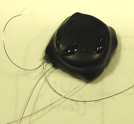
We put the transmitter in water and stirred it around. We obtained good reception with the short antenna. We recorded a one-second image, X_BW_1.daq. The average value of Y is 47008 counts and the mains hum on X is 2611 counts rms. We turned off the transmitter to let it sit for a while immersed in water. Turned on the transmitter. Average Y is 46378 counts, mains hum on X is 1566 counts. No sign of water penetration.
[22-OCT-08] Average Y is 47436 counts, mains hum on X is 410 counts. After a total of three weeks in water, we are convinced the buried wire encapsulation is water-proof.
[22-OCT-08] While encapsulating 18 transmitters this month, we were able to optimise Process X so as to reduce the time it requires, reduce the volume of the final transmitter, and yet retain the original immunity to vacuum and water. Instead of applying epoxy in several stages with syringes, immerse the transmitter in a pot of epoxy and place the entire pot in a vacuum for five minutes. We tin the connector pins before we immerse them in epoxy. The solder on the pins allows us to remove epoxy residue later. We take the transmitter out of the epoxy and put it battery-side down on a piece of non-stick plastic sheet in a petri dish. We leave it over-night at room temperature. (We get better results if we allow the epoxy to cure at room temperature. In the oven, the epoxy becomes more fluid, and runs off the transmitter too much. But we get good results if we leave the glue at room temperture for an hour and then place it in the oven at 60°C for another hour. By the end of the hour in the oven, the epoxy has cured.) The next day, the epoxy has spread across the plastic sheet, but all parts of the transmitter are covered. The battery is covered with a thin layer of epoxy, so thin we can see the battery terminal on top. We pick up the transmitter and cut the fringe of epoxy from around the battery. We take care not to cut down to the battery casing. If we do cut down to the casing, we apply some dabs of epoxy and let them dry before we continue. We file the epoxy so that the cut edges become smooth. That's it for the epoxy. Now we melt the solder on the pins and take off their thin layer of glue. We solder the steel wires in place. We dip the transmitter twice in silicone dispersion. Now the transmitter is ready.
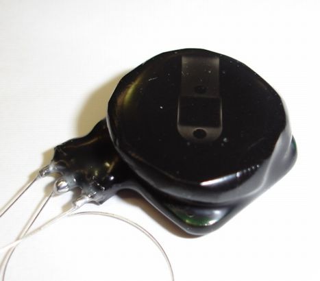
The entire process can be completed in one day, starting in the morning and with the help of an oven. The resulting transmitter volume is only 2.4 ml, compared to 2.8 ml for Process X.
[23-OCT-08] Our EP965 is a casting resin, also known as a potting epoxy. It's intended use is to encapsulate electronics in a mold, as we did earlier. In Process X, we use epoxy to fill in the cavity beneath the battery, and we apply a coating of epoxy with syringes and brushes. We decided to try some other types of epoxy. We present our results here. We start by stating the benefits of using black EP965.
Part number EP965 is a two-part epoxy casting resin made by Resinlab. It is runny when freshly-prepared (it has low viscocity). Low viscocity allows bubbles to rise through the epoxy and burst, which is essential to the vacuum steps of Process X. The casting resin shrinks very little when it cures, which means it will not create cavities in the transmitter as it cures. This particular casting resin has a 10-minute working life at room temperature, which is perfect for a ten-minute vacuum exposure, but allows the epoxy to cure quickly in a warm oven. We find EP965 is fully-cured after only an hour at 60°C. Given these superb properties, it seems to us that EP965 is ideally-suited to Process X. The epoxy is available in two colors: black and clear. We prefer black, because it's easier to see where the epxoy coat is thin when you use black epoxy. If you can see a component or solder joint through the epoxy, the epoxy is too thin and needs thickening.
Part number DP270 is a two-part epoxy casting resin made by 3M. We used the black resin, and found it to be equivalent to EP965, except that it takes longer to cure. After an hour at 60°C, it was still sticky like thick honey. After two hours the epoxy is hard.
When we tried Process X with DP270, we found each epoxy step more difficult. Over the course of half an hour, the DP270 flowed around to the bottom side of the transmitter in steps 2 and 3, making a sharp-edged flange that we had to file down when the epoxy was hard. When we painted the transmitter with DP270, it would flow down to the bottom corner of the transmitter, making a large drop, and leaving behind the areas on the top corner that needed coating. We conclude that DP270's working life is too long for our convenience in Process X.
Part number DP605 is a two-part fast-curing urethane adhesive. It cures to a flexble bond like silicone. Its working life is five minutes, and it does not sag when applied to a horizontal joint. Because it does not sag, it does not level its own surfaces, so we are left with an unattractive finish, as you can see in the picture below. Nor can we be sure that there are no cavities beneath the battery, waiting to expand once we encapsulate with silicone.
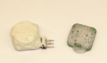
Part number 363 from Lord is a fast-curing two-part epoxy adhesive. It is runny when fresh. But after a few minutes in a vacuum, it was already hardening. It expanded with many small bubbles, but these bubbles never rose to the epoxy surface, and so remained trapped within the epoxy after we removed it from the vacuum. Some bubbles burst, but these resulted in cavities that led through the epoxy to the circuit board.
We subjected our first set of ten transmitters encapsulated with Process X to the following quality assurance program.
None of the ten transmitters failed the program.
[20-JUL-09] In Process A, we solder wires directly to the circuit board. We assume we start with a transmitter circuit that has all surface mount parts pre-loaded, but no through-hole parts. For a photograph of the finished product, see here.
If we start in the morning, we will perform the final silicone coat in the afternoon and the transmitter will be ready the next morning. Each transmitter requires an hour of labor to calibrate, encapsulate, and test. We do not need to leave the tranmsitters in water or subject them to vacuum as part of our quality assurance. No transmitter made with this process has ever leaked or suffered damage in a vacuum.
Process A protects the transmitter from damage through its vulnerable antenna connection. As we describe elsewhere, we can damage an active transmitter by applying a metal tool to its antenna connection. The transmitter may fail completely, or it may continue to function for a while. If it continues to function, we can detect the damage by measuring the voltage on the antenna output. If the voltage is VBAT instead of VCOM, damage has occurred. Process A protects the transmitter during construction by making sure that there is not battery connected to the transmitter when we solder the antenna in place. It protects the transmitter during operation by sealing the end of the antenna with a bead of epoxy.
Process A relies upon silicone to cover up any metallic parts of the circuit that may protrude through the epoxy. But we found after our first serious implant trials that the silicone rubs off sharp protrusions, leading to penetration of the encapsulation, as we can see here. The teflon insulation of the antenna and leads does not adhere to the silicone of the encapsulation, so that water penetrates easily into the epoxy and down into the solder joint, and then up any stranded wire by capillary action. Even though our wires are made of stainless steel, they still corrode slightly in the salty fluid of an animals body, and can become brittle, resulting in failure by fatigue and corrosion combined. These weaknesses in Process A lead us to Process B.
[21-NOV-17] After solving the problems of corrosion of exposed metal, or metal coated only by silicone, we discovered that corrosion also occurs within the epoxy encapsulation. If there are cavities in the encapsulation, water vapor, which penetrates both silicone and epoxy, will condense within these cavities. Water combined with electrical potential cause corrosion. When we add flux residue, the corrosion is rapid. To slow down corrosion, we are meticulous about cleaning our circuit boards before encapsulation. We encapsulate with epoxy and vacuum to eliminate cavities. Even so, ceramic capacitors are vulnerable to corrosion in humidity, so the eletronic circuit can never be immune to corrosion. In our continuous accelerated aging studies, we monitor the corrosion resistance of our devices, so that we can be sure they will not corrode while implanted before their batteries have run out.
Our MED-6607 unrestriced, medical-grade silicone cures by vulcanization with water vapor. We find that curing is reliable only when the atmosphere around the curing silicone is warm and nearly saturated with water vapor. Thus we cure our silicon in a warm, humid chamber built for the purpose.
Enamel, such as nail polish, dries in minutes to a hard, flexible solid that is resistant to hexane and alcohol, but dissolves in acetone. Our silicone dispersion is a suspension in hexane, and dissolves both paint and marker pen. But it does not dissolve nail polish. We used nail polish for several years to cover thin patches in our epoxy. When we started our accelerated aging tests, however, we found that enamel becomes brittle, changes color, and detaches from the underlying epoxy after several weeks poaching in water at 60°C. We now use epoxy, applied with a stick, to touch up thin patches.
[17-MAR-26] Ethanol damages our encapsulated devices in the following way: it penetrates the silicone and epoxy and causes the epoxy to crack and develop cavities. If we subsequently implant such a transmitter, water vapor will condense in these cavities and we will see the amplifiers acting strangely first, then the battery will drain prematurely as current consumption increases. If we get this transmitter back and dissect it, the device current consumption and sweep response might be perfectly normal, because by that time it will be dried out, although the battery will be drained. In the past two years, roughly ten of our SCTs have failed in the field due to ethanol damage. We are now making ethanol soaking warning labels to go on our encapsulated implant bags.
[18-MAR-26] See Degradation of E-60NC Epoxy by Ethanol for photographic proof of the cavities and cracks caused by ethanol after a twenty-four hour soak.
[18-MAR-26] We do not describe here in detail the encapsulation procedure that has evolved over the past ten years. We keep improving the procedure, and changing the materials every now and then. Right now we are encapsulating in E-60NC epoxy, touching up the encapsulation with DP-270, and coating the epoxy twice with MED10-6607 silicone dispersion. Suffice to say that we make every effort to eliminate cavities in the cured epoxy and silicone. We make sure the circuit boards a as clean as possible. We examine the glossy solder masks of the boards with a high-quality loupe under just the right overhead lighting to see any film left on the mask. We clean repeatedly and examine repeatedly. We use only those assembly houses that have proven over the years that they can load capacitors without cracking them. We maintain a constant accelerated aging program. We perform accelerated aging upon samples from every batch of transmitters we ship, and if one of the sample fails prematurely, we do not ship the batch, but make it again. By these means, we hope to keep corrosion failure during the life of our transmitters do less than 5%. Over the past year, the failure rate has been less than 2%, and those failures we have seen over the past two years are due to our customers soaking their devices in ethanol, which cracks the epoxy, creating the cavities needed for subsequent corrosion to cause failure.