
Figure: Results of Dissecting Fourteen Transmitters Returned from ION. We check reception (Rx %), recording of mains hum (Hum), as well as measure current consumption active and inactive, and inspect silicone for cuts.
| JAN-20 | FEB-20 | MAR-20 | APR-20 | |
| MAY-20 | JUL-20 | AUG-20 | SEP-20 | |
| OCT-20 | NOV-20 | DEC-20 |
| JAN-21 | FEB-21 | MAR-21 | APR-21 | |
| MAY-21 | JUN-21 | JUL-21 | AUG-21 | |
| SEP-21 | OCT-21 | NOV-21 | DEC-21 |
| Winter-22 | Spring-22 | Summer-22 | Fall-22 | |
| Winter-23 | Spring-23 |
Here we record our work on the development, improvement, and quality assurance of our Subcutaneous Transmitters. We begin with a summary table showing the results of our accelerated aging reliability testes. We present the various circuit board versions we have made in our pursuit of ease and reliability of encapsulation. Our day-to-day record of work starts with the introduction of the A3028 transmitter in September 2013. For earlier records of development, see A3019 (2010-2014), and A3013 (2007-2011) manual pages. For early work on encapsulation see SCT Encapsulation. For radio frequency isolation see Faraday Enclosures. For flexible leads see Flexible Wires. For comparison of electrodes see Electrodes. For work on radio frequency reception see Data Transmission and Reception.
[29-MAR-17] We started accelerated aging tests after discovering that a lot of one hundred A3028AV2 circuits was plagued by cracked capacitors as a result of excessive placement force during automated assembly. In the warmth and humidity of an animal's body, these cracks corroded and caused the capacitors to fail within a few days of implantation. Such corrosion takes place more quickly at higher temperatures, as presented in Hallberg and Peck. We began accelerated aging test in March, 2015. Since then, we have poached roughly one hundred transmitters in hot water until they failed by one means or another.
According to statistical mechanics, the rate at which a chemical reaction proceeds is proportional to e−E/kT, where T is absolute temperature, E is the activation energy of the rate-determining step in the chemical reaction, and k = 8.6×10⁻⁵ eV/K is the Boltzmann constant. We expect the mean time to failure of our subcutaneous transmitters to be proportional to eE/kT. In Hallberg and Peck, the authors show that this relationship applies well to measurements of the mean time to failure for temperatures 20-150 °C and relative humidity 20%-100% when they use an activation energy of 0.9 eV. Our devices operate at the rodent body temperature of 37°C = 310 K. When we perform an accelerated aging test at 60°C = 333 K, we expect an acceleration of ×10. At 80°C = 353 K we expect acceleration of at ×60.
We no longer keep track of all our accelerated aging tests in this document. Each transmitter we poach has its own record sheet. We have our test results up to FEB-21 in our Development Archive. At the end of each poach, we write down our diagnosis of failure. The circuit problems are identified by two-letter codes. FL is "Full Life", CC is "Corroded Capacitor", CS is "Corrosion Short", UD is "Unidentified Drain", TM is "Transmit Malfunction", TS is "Temporary Shutdown", OG is "Out Gassing", FE is "Faulty Encapsulation", CW is "Corroded Wire", FB is "Faulty Battery". If the poached transmitter had artifact problems at the beginning of the test, we enter "NA" for the first artifact time.
[23-FEB-22] See here for list of circuit versions.
See Development Archive.
See Development Archive.
See Development Archive.
See Development Archive.
See Development Archive.
See Development Archive.
See Development Archive.
[03-JAN-20] Active poaching transmitters L213.43 and L213.51 100% reception and correct response to 10-MΩ sweep. We have batch P214.6 consisting of three A3028P1 circuits equipped with ML920 batteries as IIS prototypes, 128 SPS. Frequency response P214_6. Total noise 1-40 Hz in 41°C water 4-5 μV. Switching noise <0.4 μV. We have batch S213_53 consisting of fourteen of A3028S2-DA equipped with BR1225 batteries. Ten of them displace 9.75 ml, making their average volume 0.98 ml. Frequency response P213_53 within ±1 db. Total noise 2-80 Hz in 39°C up to 16 μV due to switching noise, which consists of 10-ms spikes at 5 Hz, height 80 μV. We reject S213.65 and S213.68, leaving twelve with switching noise pulses less than 40 μV and total noise ≤12 μV, see M1578071676.ndf. We resolve to equip the S-series devices with CR1225 batteries in future, with no tabs, soldered to the circuit board directly on one edge, and with a wire to the negative tab. Both joints require acid flux, and both are best done quickly with the iron at 350°C (650F). Add S213.65 and S213.68 to active poach.
In our tests, Panasonic CR-series batteries delivered full capacity after soldering with an iron at 350°C (650F). We do not have to be quick when soldering CR-series batteries: five seconds of heating causes no degradation in battery capacity. But ML-series batteries suffer damage with a one-second application of 350°C (650F). With a 260°C (500F) iron we are able to solder directly to ML-series batteries, provided we are quick about it. If we take more than a three seconds, the battery is likely to fail. The same goes for the BR-series: a 350°C iron damages a BR-series battery, but 260°C it can tolerate for short periods. If we are not quick enough with the soldering, we will see the plastic seal bulging out between the terminals, which is a sure sign of damage and reduced capacity. We resolve never to solder ML or BR-series batteries, but to get them equipped with tabs, which we bend and shape so as to mate with pads on our circuits. When we use CR-series, we choose the battery that is most convenient: we can solder directly or use tabs. When we solder, we do so quickly with acid flux and our iron at 350°C (650F).
[06-JAN-20] Active poaching transmitters L213.43, L213.51, S213.65, and S213.68 100% reception, response to 20-MΩ sweep correct.
[07-JAN-20] Active poaching transmitters L213.43, L213.51, S213.65, and S213.68 100% reception.
[08-JAN-20] Dissect E201.124 returned from ION, made from A3028RV2 circuit. Silicone and epoxy in good condition. Inactive current 1.8 μA. Active current 3 mA rising to 5 mA over several minutes. Reception 100%. Remove C3 and C4, no change. Diagnosis: "Unidentified Drain".
[10-JAN-20] We have batch E213_67 consisting of 14 of A3028E-AA. Response to 20-MΩ sweep E213_67.gif within ±0.7 dB. Total noise 2-160 Hz in 39°C water is ≤6 μV and switching noise ≤2 μV except for E213.74, which has total noise 10 μA and switching noise 3 μV. Active poaching transmitters L213.43, L213.51, S213.65, and S213.68 100% reception, response to 100-kΩ sweep correct. Add E213.74 to poach.
[13-JAN-20] Active poaching transmitters L213.43, L213.51, S213.65, S213.68, and E213.74 100% reception.
[16-JAN-20] Active poaching transmitters L213.43, L213.51, S213.65, S213.68, and E213.74 100% reception. Response to 20-MΩ sweep correct except for S213.68, which shows some step noise during sweep. Response to 100-kΩ sweep correct for S213.68.
[18-JAN-20] We have five A3028GV1 circuits that passed calibration but all failed before encapsulation with the same symptom: 16 mA current consumption, does not turn on or off. One failed quality control. Four passed quality control and failed after battery loading. On all five boards, removing U9 MAX2624 stops the excessive current consumption. We replace U9 on four boards and get correct current consumption and 100% reception. We are unable to salvage two boards because we have already removed U3, and find ourselves unable to \replace U3. We salvage three board, check their new RF spectra, and find them centered in 913-918 MHz. We recall that the MAX2624 is sensitive to large metal objects touching its antenna output while it is turned on. We hypothesize that U9 is suffering damage in this way during assembly and calibration. Active poaching transmitters L213.43, L213.51, S213.65, S213.68, and E213.74 100% reception.
[20-JAN-20] We have the following report from dissections of transmitters returned from ION. As noted above, E201.124 has excessive current consumption and won't transmit. We are unable to identify a point of corrosion in the circuit. We note black dots and bubbles in the silicone at the base of the leads.
Two of the transmitters are fully-functional upon return. With their original batteries connected, we get 100% reception, full RF power observed with Spectrometer, RF center frequency correct, and response to 20-MΩ sweep is correct. We have batch A213.69 consisting of six A3028A-CCC. Response to 20-MΩ sweep A213_69 within ±0.4 dB. Total noise 2-160 Hz in 40°C water ≤12 μV, switching noise ≤4 μV.
Active poaching transmitters L213.43, L213.51, S213.65, and E213.74 100% reception. But S213.68 has stopped. Dissect. VB = 3.0 V because battery is hot. Disconnect. Notice that the 0V wire comes away from the board easily. Connect external 2.7 V. Inactive 0.8 μA, active 45 μA, 100% reception. Diagnosis "Corroded Wire".
[24-JAN-20] We have batch E213_121 consisting of 8 of A3028E-AA. This batch has suffered from five or six failures of U9 during encapsulation. Three of them, 126, 129, and 133 have U9 replaced. Frequency response E213_121 within ±0.4 dB. Total noise 2-160 Hz in 41°C water is ≤8 μV, switching noise ≤3 μV. We have batch C213_85 consisting of eleven of A3028C-CC. Frequency response C213_85 within ±XX dB. Total noise 2-80 Hz in 37°C water is ≤8 μV, switching noise ≤4 μV, except C213_94 12 μV total and 8 μV switching. Reserve C213_94 for poaching.
[27-JAN-20] Active poaching transmitters L213.43, L213.51, S213.65, and E213.74 100% reception and response to 20-MΩ sweep correct.
[28-JAN-20] Active poaching transmitters L213.43, L213.51, S213.65, and E213.74 100% reception. Add C213.93 to poach.
[29-JAN-20] Active poaching transmitters L213.43, L213.51, S213.65, E213.74, and C213.93 100% reception.
[31-JAN-20] We have batch E213_183 consisting of five A3028E-AA. Frequency response E213_183 within ±0.4 dB. Total noise 2-160 Hz in 37°C water is ≤8 μV, switching noise ≤4 μV. Active poaching transmitters L213.43, L213.51, S213.65, E213.74, and C213.93 100% reception. Response to 20-MΩ sweep correct.
[03-FEB-20] Active poaching transmitters L213.43, L213.51, S213.65, E213.74, and C213.93 100% reception.
[04-FEB-20] Active poaching transmitters L213.43, L213.51, S213.65, E213.74, and C213.93 100% reception.
[07-FEB-20] Active poaching transmitters L213.43, L213.51, S213.65, E213.74, and C213.93 100% reception.
[09-FEB-20] Active poaching transmitters L213.43, L213.51, S213.65, E213.74, and C213.93 100% reception, response to 20-MΩ sweep correct except S213.65, which shows −10 dB gain at 80 Hz and occasional step artifacts.
[11-FEB-20] We have batch C213_98 consisting of 9 of A3038C-CC. Frequency response C213_98 within ±0.7 dB. Total noise 2-80 Hz in 40°C water is ≤7 μV, switching noise ≤2 μV. Active poaching transmitters L213.43, L213.51, S213.65, E213.74, and C213.93 100% reception.
[12-FEB-20] Active poaching transmitters L213.43, L213.51, C213.93, E213.74, 100% reception. Device S213.65 has stopped. Diagnosis "Full Life".
[14-FEB-20] We have C213.189 and C213.190 we add to our earlier batch C213_98 of A3028C-CC. Add frequency response to C213_98. Total noise 2-80 Hz in 37°C water ≤7 μV, switching noise ≤2 μV. We have batch Q213_135 consisting of 8 of A3028Q-NDB. Frequency response Q213_135 within ± 0.3 dB. Total noise 2-320 Hz in 41°C water ≤12 μV, switching noise <0.4 μV.
[18-FEB-20] Active poaching transmitters L213.43, L213.51, C213.93, E213.74, 100% reception.
[21-FEB-20] Active poaching transmitters L213.43, L213.51, C213.93, E213.74, 100% reception. Response to 100-kΩ sweep correct.
[24-FEB-20] Active poaching transmitters L213.43, L213.51, C213.93, E213.74, 100% reception.
[28-FEB-20] Active poaching transmitters L213.43, L213.51, C213.93, E213.74, 100% reception.
[03-MAR-20] Active poaching transmitters L213.43, L213.51, C213.93, E213.74, 100% reception. Response to 100-kΩ sweep correct except for L213.43 has gain 6 dB too low at 60 Hz on X input.
[06-MAR-20] Active poaching transmitters L213.43, L213.51, E213.74, 100% reception. C213.93 has stopped. Diagnosis "Full Life".
[09-MAR-20] Active poaching transmitters L213.43, L213.51, E213.74, 100% reception, noise ≤8 μV.
[10-MAR-20] We have batch Q213_153 consisting of 12 of A3028Q-NDB. Frequency response Q213_153 within ± 0.3 dB. Total noise 2-320 Hz in 37°C water ≤10 μV, switching noise <0.4 μV.
[13-MAR-20] We have batch B211_43 consisting of 14 of A3028B-AA with 55 mm leads. Frequency response Q211_43 within ± 0.6 dB. Total noise 2-160 Hz in 37°C water ≤10 μV, switching noise <4 μV. Active poaching transmitters L213.43, L213.51, E213.74, 100% reception, noise ≤8 μV. Response to 100-kΩ sweep correct for E213.74, but L213.43 gain 6 dB too low at 60 Hz on X input and L213.51 reads 25±2 counts.
[20-MAR-20] Active poaching transmitters L213.43, L213.51, E213.74, 100% reception, noise ≤8 μV.
[23-MAR-20] Active poaching transmitters L213.43, L213.51, E213.74, 100% reception, noise ≤8 μV. We have batch C213_193 consisting of 21 of A3028C-DC. Frequency response C213_193 within ±0.7 dB. Noise 2-80 Hz in 37°C water ≤10 7 μV, switching noise ≤4 μV, except C213_210, switching noise 8 μV, don't ship.
[26-MAR-20] We have batch C207.169 consisting of 17 of A3028C-AA. Frequency response C207_169 within ±0.9 dB. Noise 2-80 Hz in 37°C water ≤6 μV, switching noise ≤4 μV.
[27-MAR-20] We have batch C207.188 consisting of 17 of A3028C-AA. Frequency response C207_188 within ±1.0 dB. Noise 2-80 Hz in 37°C water ≤6 μV, switching noise ≤4 μV. We hold back No189 because of a bubble in silicone.
[27-MAR-20] Active poaching transmitters L213.43, L213.51, E213.74, 100% reception, noise ≤8 μV. Response to 100-kΩ sweep correct for E213.74, but L213.43 X-gain 6 dB too low at 60 Hz and L213.51 X reads 25±2 counts. Add C213.197 (replaced yellow lead) and C213.210 (noisy) to poach.
[31-MAR-20] Active poaching transmitters L213.43, L213.51, E213.74, C213.197, and C213.210 100% reception, noise ≤8 μV. Response to 100-kΩ sweep correct for E213.74, E213.74, C213.197, and C213.210.
[01-APR-20] We have batch B200_200 consisting of 17 of A3028B-AA. Frequency response B200_200 within ±0.4 dB. Noise 2-160 Hz in 37°C water ≤10 μV, switching noise ≤4 μV. Active poaching transmitters L213.43, L213.51, E213.74, C213.197, and C213.210 100% reception, noise ≤8 μV
[07-APR-20] Active poaching transmitters L213.43, L213.51, E213.74, C213.197, and C213.210 100% reception, noise ≤8 μV.
[10-APR-20] Active poaching transmitters L213.43, L213.51, E213.74, C213.197, and C213.210 100% reception, noise ≤8 μV.
[13-APR-20] Active poaching transmitters L213.43, L213.51, E213.74, C213.197, and C213.210 100% reception, noise ≤8 μV. Response to 100-kΩ sweep correct for channel numbers 44, 74, 197, 210, incorrect for 43, 51, and 52.
[15-APR-20] Active poaching transmitters L213.43, L213.51, E213.74, C213.197, and C213.210 100% reception, noise ≤8 μV.
[18-APR-20] Active poaching transmitters L213.43, L213.51, E213.74, C213.197, and C213.210 100% reception, noise ≤8 μV.
[21-APR-20] Active poaching transmitters L213.43, L213.51, C213.197, and C213.210 100% reception, noise ≤8 μV. E213.74 has stopped.
[23-APR-20] Active poaching transmitters L213.43, L213.51, C213.197, and C213.210 100% reception, noise ≤8 μV.
[24-APR-20] We have batch B200_220 consisting of 16 of A3028B-AA. Frequency response B200_200 within ±0.4 dB. Noise 2-160 Hz in 37°C water ≤10 μV, switching noise ≤4 μV, except P200_202 noise ≤12 μV. We dissect E213.74. VB = 1.0 V. Disconnect battery, use external 2.7 V. Inactive current 1.7 μA, active 90 μA for a few seconds, then 1.6 mA. Increase supply to 4.0 V and current increases to 3.0 mA. Diagnosis "Corroded Capacitor", probably C1 or C3.
[27-APR-20] Active poaching transmitters L213.43, L213.51, C213.197, and C213.210 100% reception, noise ≤8 μV.
[28-APR-20] Active poaching transmitters L213.43, L213.51, C213.197, and C213.210 100% reception, noise ≤8 μV.
[01-MAY-20] Active poaching transmitters L213.43, L213.51, C213.197, and C213.210 100% reception, noise ≤8 μV. Response to 100-kΩ sweep correct or C213.197. L213.51, C213.210 VA near 2.2 V, no dynamic range for sinusoidal response. L213.43 has stopped. Add B216.2, noisy device, to poach.
[05-MAY-20] Active poaching transmitters L213.51, C213.197, B216.2, and C213.210 100% reception, noise ≤8 μV, but C213.197 and C213.210 VA near 2.2 V.
[06-MAY-20] Active poaching transmitters L213.51 and B216.2 100% reception, noise ≤8 μV. Devices C213.197 and C213.210 have stopped. Diagnosis "Full Life".
[15-MAY-20] We have distributed the chore of checking the poaching transmitters, so will be reporting only diagnoses here. On 12-MAY-20 L213.51 stopped working after being left out for several hours. Today it is again working, but we dissect all the same. VB = 2.7 V. Attach external 2.7 V. Active 259 μA, inactive 2 μA. Diagnosis "Temporary Shutdown". Dissect L213.43. VB = 0.1 V. External 2.7 V, active 268 μA, inactive 3 μA. Diagnosis "Unidentified Drain".
[29-JUL-20] We have batch U217_9 consisting of 7 of A3028U-AAA. We measure frequency response U227_9. Our function generator has a DC offset of +1.5V or thereabouts, which takes the A3028U input too close to the top for us to measure a good-sized sinusoid, so we connect the input leads the other way around from usual, and the input moves down, in which direction it has more room to move. Gain within ±1.5 dB, which is at the limit of our specification, and occurs in the range 10-100 Hz. Switching noise <8 μV, total noise 1-160 Hz ≤25 μV in 37°C water. We have batch P204_54 consisting of 13 of A3028P1-AA. Frequency response P204_54 within ±0.7 dB except for No68 which has wandering baseline. No54 has visible white corrosion around the battery. The rest have negligible switching noise and total noise 1-80 Hz of <4 μV.
[17-AUG-20] Dissect U217.9 failed at 12 days poach 60°C. VB=0.5V, disconnect, VB=1.5V. Connect external 2.7 V. Active current 145 μA reception 100%, inactive 1 μA. Diagnosis: "Full Life".
[27-AUG-20] Dissect P204.57. Visible corrosion around battery edge. Remove battery, VB=0.2V. Connect external 2.7 V, active current 35 μA, device is fully-functional. Diagnosis "Corrosion Short".
[04-SEP-20] We have batch E203_81 consisting of 17 of A3028E-DA. Response to 100-kΩ sweep within ±0.7 dBm is E203_81. Switching noise <3 μV, total noise 1-160 Hz ≤12 μV in 37°C water.
[07-SEP-20] Poaching transmitter P204.54 has stopped. Remove silicone. Thin layer of epoxy around battery has crumbled, but see no sign of corrosion. Beneath the label, the interface between the epoxy and the battery is tacky. When we touch with iron, it generates acrid smoke. Remove battery and connect external 2.6 V. Active current 35 μA, inactive 0.8 μA. Diagnosis "Full Life". We put E203.98 and E203.99 in to poach.
[01-OCT-20] We have batch B205_44 consisting of 12 of A3028B-DD. Response to 20-MΩ sweep within ±0.5 dBm is B205_44. Switching noise <4 μV, total noise 1-160 Hz ≤12 μV in 37°C water. Rust on No45 and No49 due to imperfect encapsulation of battery tab corners precludes shipping. Two others 50 and 55 have traces of rust, but now tabs are well-covered and we decide to ship them.
[02-OCT-20] We have batch B213_217 consisting of 14 of A3028C-CC. Response to 20-MΩ sweep within ±1.0 dBm is B213_217. Switching noise in 37°C water <4 μV, total noise 1-80 Hz ≤10 μV.
[12-OCT-20] We have four A3028T1-R made two years ago that have been sitting on the shelf. They will not turn on. We charge with A3033B, which provides 4.2 V in series with 1 kΩ and wait four hours, still no reception, but when we connect 4.2 V through an ammeter, with no series resistor, we see 3 mA flowing in, and we have good reception. We turn off with magnet, see 0.7 mA flowing in. Disconnect 4.2 V and get reception for a few minutes. We see the same thing for the other three devices. After two years draining the battery, none of them draw more than 0.8 mA from 4.2 V.
[19-OCT-20] We have batch H207_209 consisting of 17 of A3028H-AAA. Frequency response H207_209 within ±1.2 dB. Noise 1-80 Hz in 37°C water is <12 μVrms, with most channels being around 7 μV rms. Switching noise ≤4 μV.
[26-OCT-20] We have two A3028C-CC that won't turn on after epoxy encapsulation. Batteries are both drained. Current consumption from external 2.6 V is 17 mA for both, no signal received, no change when we apply magnet. Replace U9, MAX2624, on one, and now we see 52 μA active current consumption and 100% reception. These failures appear to be identical to those we began to encounter in January.
[30-OCT-20] We have batch C217_25 consisting of ten of A3028C-CC. Frequency response C217_25. Total noise in 37°C water ≤10 μV, switching noise ≤2 μV.
[09-NOV-20] We have batch H218_23 consisting of 18 of A3028H-AAA. Frequency response H207_23_A and H207_23_B within ±1.0 dB. Noise 1-80 Hz in 37°C water is <9 μVrms. Switching noise ≤3 μV.
[14-DEC-20] We have batch C217_39 consisting of 14 of A3028C-CC. Frequency response C217_39 within ±0.8 dB. Total noise in 37°C water ≤10 μV, switching noise ≤3 μV.
[16-DEC-20] We begin layout of the A302801H printed circuit board, which will be the basis of a new two-channel A3028H assembly, schematic S3028H_1. Changes with respect to the previous A3028GV1 are as follows. Replace U8 LC4064ZC in 6-mm × 6-mm BGA-56 with LC4064ZE in 5-mm × 5-mm BGA-64 as used on A3028PV1. Replace obsolete ASH7KW oscillator with new ASTMTXK in ASTM package, as used on A3028PV1. Replace unreliable and impossible to hand-replace SN74AUP1G80 in UDFN-6 with same device in SOT-353. Replace obsolete SL353LT in SOT-23 with S5712A in smaller SNT-4 package. Remove series resistors R25 and R26, as well as RF filtering capacitors C17 and C18. Add recharging diodes D1 and D2 in P0402 packages, as on A3028PV1.
[26-DEC-20] We solder 10-KΩ resistors to both terminals of two CR1225 coin cells using acid flux and a 650F iron. One battery is by Celewell, the other by Wama. With 300 μA flowing into the resistor we expect the 48-mAhr batteries to last for 7.4 days. Two days later we find them exhausted. The seal between the battery tabs of both batteries is bulging and the battery surface tastes like soap. We mount two more batteries in holders and solder the resistors to the holders. It is 4 pm 26-DEC. We solder BR1225 with side tabs (Digi-Key P290) to pup transmitter circuit boards by bending the tabs. They come out fine, and we are not heating the battery.
[28-DEC-20] The two CR1225 batteries in holders with 10-kΩ loads are at 2.8 V after 2 days at 300 μA.
[29-DEC-20] We have batch C217_81 consisting of 11 of A3028C-CC. Frequency response C217_81 within ±0.7 dB. Noise 1-80 Hz in 37°C water is <12 μVrms. Switching noise ≤4 μV.
[13-JAN-21] We have MAX2624 made by Rochester Electronics. We load one onto an A3014MT modulating transmitter and re-wire the tuning input to the !SHDN pin on the chip. We trim the TUNE input to give 915 MHz and mix the output through −10 dBm with +7 dBm of 900 MHz. We view IF terminated with 50 Ω on our scope along with a 3.3-V shutdown signal, to see if the duplicate part can turn on and off fast enough.

We do the same with the MAX2624 made by Maxim Integrated Circuits.

We are confident the Rochester part will be a drop-in replacement for the Maxim part we have been using for the past fifteen years.
[24-JAN-21] We receive first article of five pieces of A3028HV1 from our assembly house. The boards function perfectly, with the exception of one lifted pin, shown below, which we fix easily.

Inactive current consumption is 0.8 μA. Active current consumption at 512 SPS is 72 μA, compared to 79 μA for the A3028GV1. We can expect a 10% increase in operating life for all SCTs made with this circuit, and a doubling of shelf life. We have batch B205_62 consisting of 12 of A3028B-DD. Frequency response B205_62 within ±0.5 dB. Noise 1-160 Hz in 37°C water is <12 μVrms. Switching noise ≤4 μV.
[26-JAN-21] We have batch S217_56 consisting of twelve of A3028S2-DA with 45-mm x 0.5-mm leads and 13-mm helical antenna. The D-pin termination is missing on three devices, No62, 66, and 70. They are loaded with BR1225 batteries by bending and soldering tabs, rather than by soldering directly to the battery. We decided against soldering directly to BR-series batteries because they are easy to damage with the iron. We purchased CR1225 batteris with no tabs from two non-Panasonic manufacturers, and these proved to be vulnerable to soldering as well, unlike the CR-series batteries made by Panasonic. Frequency response S217_56 within ±0.7 dB, total noise in 37°C water is ≤12 μV in 1-80 Hz, but we see significant switching noise because of the high source resistance of the BR-series batteries. See M1611697994.ndf for today's recording at roughly 37°C from the entire batch. We reject S217_70 for 8 μV amplitude, 5-Hz switching noise. The rest have switching noise 0-5 μV and are ready to ship. We order these CR1225 batteries from Renata via Digi-Key in the hope they may prove as resistant to soldering as the Panasonic CR-series batteries.
[27-JAN-21] We place batch S217_56 in water again, this time starting with 48°C, and record. Switching noise in the worst offender, S212_70, is now zero. At 40°C, No70's switching noise has risen to 2 μV, and appears as 50-μV pulses at 5 Hz. We allow water to cool to 38°C and record for five minutes, by which time the temperature has cooled to 36°C, see M1611772233.ndf. We note that the pulses in No66 are opposite to those in the rest of the devices. We are struck by the absence of low-frequency noise in the three devices with soldered pins missing, compared to continuous rumble from those with pins.
[29-JAN-21] We have batch S219_74 consisting of 11 of A3028S2-DA. Frequency response is 0.3-40 Hz instead of 0.3-80 Hz, so we must reject them all, see S219_74. Noise in 37°C water is ≤12 μV and switching noise is ≤5 μV, except S217_99, which is 8 μV and we reject for that reason.
[03-FEB-21] We have batch B205_76 consisting of 9 of A3028B-DD. Frequency response B205_76 within ±0.3 dB. Noise in 37°C water is ≤5 μV rms, except No83 which is 8 μV because of switching noise fundamental of 4 μV. Switching noise of remainder is <2 μV.
[04-FEB-21] We have CR1225 from Renata Batteries, via Digi-Key. We use 650F iron and acid flux to put two solder blobs on one sample, clean it up, put it in battery holder with 10 kΩ load. We put an un-altered battery in another holder. Both have voltage 3.1 V. It is 14:03. We expect 178 hrs battery life.
[12-FEB-21] We have two more boards with the symptoms recorded on 18-JAN-20, "16 mA current consumption, does not turn on or off".
[15-FEB-21] We have batch H218_65 consisting of 15 of A3038H-AAA-B45-B made with the last of our A3028GV1. Volume of 10 is 12.0 ml. Thickness 7.7 mm, same as two earlier devices we have left from a previous batch. Frequency response H218_65 within ±0.5 dB. Noise in 37°C water 2-80 Hz is ≤7 μV, switching noise <2 μV, except for H218_89, for which noise is 11 μV and switching noise is 4 μV, hold it back for poaching, 500-s archive is M1613410322. We have batch B216_14 consisting of 15 of A3028B-AA-B45-B. Volume of 10 is 12.2 ml. Frequency response B216_14 within ±0.5 dB. Noise in 37°C water 2-160 Hz is ≤8 μV and switching noise ≤2 μV except B216.23, for which noise is 12 μV and switching noise is 5 μV. Our two CR1225 batteries have run down. Both batteries were >2.3 V after 170 hrs. The un-heated battery was 2.3 V after 190. The heated battery had dropped to 1.9 V. At 300 hrs, both are at 20 mV. We conclude the battery capacity is near 48 mAhr.
[17-FEB-21] We load three CR1225 batteries onto three A3028PV1 circuit boards programmed as A3028S5, 2048 SPS, current consumption 230±2 μA. We use acid flux and 650F iron, see CR1225_Soldering video. Place in Faraday enclosure, unencapsulated, noise in 2-160 Hz is 5-6 μVrms, switching noise less than 0.4 μV. We leave running in an enclosure, recording battery voltage.
[19-FEB-21] We have batch C218_99 consisting of 17 of A3028C-AA-B45-B. This is the first batch of transmitters made with the new A3038HV1 assemblies, which are 0.5 mm shorter, and have the battery 0.2 mm closer to the circuit board. Volume of 10 pieces is 10.6 ml. Outer dimensions 13.3 mm × 13.3 mm × 7.5 mm. Previous A3028C made with A3028GV1 was 13.5 mm × 14.5 mm × 7.5 mm. Noise in 37°C water is dominated by 5-Hz switching noise with amplitude up to 6 μV and total noise 2-80 Hz is up to 15 μV rms. Three have total noise >12 μV rms, see first eight-second interval in M1613781261.ndf. Minimum noise is only 4 μV rms. We reject No101 (15 μV rms) and No104 (13 μV rms). At the end of the archive, the water has cooled to around 30°C and the noise in No116 has increased from 10 μV rms to 16 μV rms. See original study of switching noise versus temperature here. We order 100 of CR1223AH by Renata, looks like this, with mounting pins suitable for hand-soldering, but "not suitable for reflow soldering", which makes them perfect for us, they are a drop-in replacement for the BR1225AHB.
[22-FEB-21] Of three soldered CR1225 we left running, one has dropped to 2.2 V and the other two are still going strong with 2.6 V after 115 hours, when we expect 209 hrs operating life.
[26-FEB-21] S217.59 failed after 24 days poaching. Battery 1.0 V. Disconnect battery. Connect external 2.7 V. Active current 46 μV, inactive 0.8 μV. Diagnosis "Unidentified Drain". We have batch S218_119 consisting of 13 of A3028C-AA-B45-B. We place in water at 40°C and record as water cools to 36°C, recording is M1614369326.ndf. Switching noise pulses vary from <1 μV to 10 μV. We reject the three with the greatest noise, leaving eight with pulses <1 μV and two with pulses of 5 μV.
[01-MAR-21] We have the completed battery drain for our three soldered CR1225 batteries from Renata. Plot of battery voltage versus time, as deduced from transmitters with 230 μA active current is here. Expected life 208 hrs. Actual live 110, 170, and 200 hrs.
[03-MAR-21] We acquire a Sunkko 788H spot-welding machine. We cut thin nickle strips and weld them to Renata CR1225 batteries. We use 40 V, 2 pulses, and 50% power. We are pressing the nickle and battery up against the two welding electrodes attached to the welding unit. The nickle strips are 100 μm thick. We solder the nickle strips to our three A3028S5 circuits. Switching noise pulses 2 μV in No226, not visible in the other two.

We place A3028S5s in Faraday enclosure to run down their batteries at 230 μA.
[04-MAR-04] We spend some more time spot-welding, this time with the extension leads to hand-held electrodes. We have 100-μm thick nickle strips. We cannot get strong welds with 40 V, 2 pulses. But we do get strong welds with 80 V, 1 pulse. One in five welds does not produce strong joints. We switch to 2 pulses and every weld is strong. When we switch to 150-μm nickle, all bonds are weak, no matter how hard we press. We cannot weld 150-μm nickle to 150-μm nickle, but we can weld 100-μm nickle to 150-μm nickle.
[05-MAR-21] We have fifteen unencapsulated A3028C-AA-B45-B loaded with CR1225AH batteries. No12 is GV1 circuit, the rest are HV1. Turn them all on and put in 60°C oven for ten minutes, remove to Faraday enclosure and start recording for ten minutes as they cool down, see M1614972869.ndf. Throughout recording, switching noise fundamental is <2 μV. Total noise 2-80 Hz ≤5 μV rms.
[10-MAR-21] We have batch B212_12 consisting of 15 of encapsulated A3028B-AA-B45-B made with A3028HV1 and CR1225AH battery. No22 shows rust stain in water and we find a breach in the silicone on the battery rim. The silicone on all rims is 200 μm over epoxy of 100 μm, so far as we can tell. We turn all on and place in 37°C water. No visible switching noise, except in No22, which shows sharp 5-Hz spikes of 30 μV when we immerse the breach in the water with the leads. Volume is 1.0 ml. We are going to apply more silicone.
[11-MAR-21] Our spot-welded Renata CR1225 have run down their batteries after 220 hours, where expected life is 208 hrs.
[14-MAR-21] After one additional coat of MED-6607, batch B212_12 encapsulation looks rugged and thick. Volume is 16.5 ml for 15 = 1.10 ml, up from 1.0 ml prior to the final coat. We see antenna noise on No22 at first, but the noise does not persist. No19 has deformed silicone on battery rim due to previous breach. Frequency response B212_12 within 0.25 dB. Noise 2-160 Hz is 4-5 μVrms. Switching noise in 37°C water is <0.4 μV, see M1615748047.ndf.
[15-MAR-21] We have batch C217_110 consisting of 15 of A3028C-CC-B45-B, made from A3028HV1 with CR1225AH batteries, one coat of MED10-6607 plus three coats of MED-6607. Volume of 12 is 13 ml, individual volume 1.08 ml. Outermost dimensions 13.5 × 12.9 × 7.3 mm3. Frequency response C217_110, switching noise in 37°C water is <0.4 μV and total noise 2-80 Hz is ≤9 μV rms (note: soldered screw electrodes).
[18-MAR-21] We have C218.124 encapsulated in epoxy with one coat of SS-5001 and one coat of MED-6607. Volume 1.3 ml, looks rugged. We have a batch of 12 of A3028C-AA-B45-B encapsulated in epoxy with three coats of MED-6607. Volume of 12 is 12.8 ml, 1.07 ml each. After comparing these devices to older ones made with the A3038GV1 circuit, we decide to coat them once more.
[22-MAR-21] Batch B212_29 consists of twelve of A3028B-AA-B45-B with four coats of MED-6607. Volume 1.14 ml. Frequency response B212_29, total noise 1-160 Hz in 37°C water is 5-6 μV rms, switching noise cannot be detected at all, even in 16-s intervals.
[25-MAR-21] Batch H205_89 consists of eight of A3028H-DAA-B90-B with four coats of MED-6607. Mass 20.20 g ÷ 8 = 2.52 g. Volume 9.9 ml ÷ 8 = 1.23 ml. Frequency response H205_89. Total noise in 37°C water is 5-6 μVrms for Y with bare wire and ≤12 μV for X with soldered D-pin, no sign of switching noise.
[31-MAR-21] We have batch E203_100 consists of 18 of A3038E-DA-B150-A equipped with BR2330 batteries and built with A3038HV1 circuit boards. We have some trouble constraining the leads during rotation and cutting the programming extension after epoxy encapsulation. Mass 5.9 g for one, volume 31 ml for ten, making each 3.1 ml. Frequency response E203_100, total noise in 37°C water 2-160 Hz is ≤10 μV, switching noise ≤4 μV.
We construct the first A3038J prototype, 3-200 Hz passband with differential amplifier input and a Y− lead. We connect 100-kΩ, 30-mVpp sweep to Y+/Y− and see 7000 counts rms amplitude, or 28 mVpp with the prototype sensitivity of 1.4 μV/cnt. Frequency response is roughly 3-200 Hz, with a single-pole filter on either end. We connect the same signal as common-mode to both Y+ and Y−, while connecting the signal ground to C, and see 71 counts rms amplitude. Our common mode rejection ratio is 100, or 40 dB.
[05-APR-21] We have two A3028J prototypes with all four leads and antennas loaded. We connect X+, Y+, Y− to a 10-Hz sinusoid and X− to signal ground. In No1 we see 12162 counts rms on X, meaning 5.0 mV rms, and 67 counts rms on Y, meaning 93 μV rms. Common mode rejection ratio is 54. In No3 we see 5 mV and 70 μV for CMRR 71.
[07-APR-21] Batch H205_107 consists of eight of A3028H-DAA-B45-B made with A3028HV1 and CR1225AH. No switching noise, total noise less than 10 μV when we ignore chemical artifact generated by the D-pins. Frequency response H205_107.
[07-APR-21] We have an A3028E-DA-B150-A made with CR2430AH 285-mAhr battery, E203_119. Volume is 3.2 ml, mass 6.7 g. We have three of the same type made with BR2330 255 mAhr batteries, volume 3.2 ml and mass 5.8 g. Frequency response E203_119. No sign of switching noise in E203_119 or E203_122, but E203_120 and E203_121 have harmonics of amplitude 2 μV. Total noise 2-160 Hz is ≤10 μV rms, dominated by the low-frequency rumble we associate with soldered D-pins.
[12-APR-21] We have two A3028J-AAAA-B45-B made with CR1225AH and A3028HV1. Response to 16 mVpp sweep is J203_1.
[15-APR-21] We have batch C217_129 consisting of eight A3028C-CC-B45-B made with CR1225AH and A3028HV1. Frequency response C217_129.gif. Noise in 1-80 Hz in 37°C water 5-6 μV rms. No sign of switching noise.
[28-APR-21] We have batch C217_137 consisting of twelve A3028C-CC-B45-B made with CR1225AH and A3028HV1. After three coats of silicone, volume was 1.0 ml. No140 had a breach in silicone over battery tab, which causes sinusoidal waves in Y. No142 had fiberglass spike. After a fourth coat, volume is 1.12 ml. Frequency response C217_137.gif. Noise in 1-80 Hz in 37°C water 5-6 μV rms. No sign of switching noise.
[02-MAY-21] We have batch C217_152 consisting of 13 of A3028C-CC-B45-B. After three coats of MED-6607 they are 1.04 ml with sharp corners on the battery rims and tabs. After four coats they are 1.13 ml, all surfaces are rounded and silicone looks thick and tough. Frequency response C217_152. Total noise 2-80 Hz 4-7 μV rms, no sign of switching noise.
[06-MAY-21] We have batch L217.183 consisting of 12 of A3028L-AAA-B150-A. Volume of 6.0 ml. Response to 20-MΩ sweep L217_183. Noise in 37°C water 2-320 Hz is 6-8 μV rms. No sign of switching noise. Place all twelve in an FE3A with four antennas, spread them out on shelf, and see 10% loss due to collisions.
[04-JUN-21] We equip three A3028S2 transmitters with 25-mm, 35-mm, and 50-mm helical lead loop antennas. We are using our 0.7-mm diameter helical lead with clear silicone and we are holding the tip of the loop to the transmitter body opposite the input leads using a rubber band. We use an A3038A tracker and an A3027E receiver to compare reception in air and water for these three and two A3028S2 with the established 13-mm helical straight antenna. We are operating out on our bench in the presence of interference. In air, the 35-mm loop does well, reception twice as good as 13-mm straight and slightly better than 50-mm loop. In water, the 13-mm straight appears to be best, but only marginally so.
[05-JUN-21] We move our A3028S2 reception test into our Faraday canopy (FE5A). We have five transmitters. We hold each in hand with antenna in air and move over the entire extent of the A3038A platform from height 1 cm to 10 cm and estimate reception by watching the ALT's reception light. We move slowly so as to allow the light to turn off in a reception dead spot. We repeat with the transmitter in the bottom of a beaker, its antenna resting upon the glass. All antennas are made of our 450-μm diameter 316SS springs, MDC13867A. No74, 13-mm straight, 95% in air, 100% in water. No55, 13-mm straight, 50% in air, 98% in water. No92, 25-mm loop, 100% in air, 98% in water. No75, 35-mm loop, 75% in air, 98% in water. No97, 50-mm loop, 100% in air, 95% in water.
[11-JUN-21] We test reception from S217.55 (equipped with C-antenna) and C217.152 (equipped with B-antenna) over an A3038A tracker platform. We place each transmitter on its own in a 50-ml beaker and move the beaker around over the platform, rotating at random. We start with no water, then add water in increments and repeat. We are estimating reception with the Receiver Instrument.

We perform the above experiments in an FE3A enclosure with the door open. When we encounter poor reception, we close the door to check if the problem is interference. Poor reception arising from water volume 10-20 ml does not improve when we close the door. We perform the above experiment in front of an A3015C antenna connected to an A3027E and measure reception with the C-antenna moving 5-30 cm away. For 0 ml of water we get 80% reception, for 15 ml we get 50%, and for 40 ml 95%. According to Oregan State University, dissolved salt greatly increases the loss factor of a water dielectric. In our Faraday canopy we start with S217.55 in 40 ml of 1% saline, watching the ALT reception indicator. We estimate 50% reception. As we reduce the volume of saline down to 0 ml, reception rises to 100%.
[18-JUN-21] We have batch C217_211 consisting of thirteen A3028C-CC-B45-B. Silicone is discolored and patchy, but otherwise robust and tough. Frequency response C217_211. Total noise in 37°C water ≤8 μV, no sign of switching noise.
[24-JUN-21] We have batch C219_2 consisting of fourteen A3028C-CC-B45-B. Silicone is perfect. Frequency response C219_2 within ±0.8 dB. Total noise in 37°C water ≤8 μV, no sign of switching noise. Volume 1.09 ml.
[28-JUN-21] Complete the A302801K layout, Revision 1 for the A3028KV1 assembly, schematic S3028K. The new assembly has the same outline as the A3028HV1, but uses the LC4064ZC-75M56C in BGA-56, the same chip we used in the A3028GV1 and earlier circuits. We just obtained 3400 pieces at a good price. The BGA-56 is 6 mm × 6 mm, compared to 5 mm × 5 mm for the BGA-64 we use on the A3028HV1. To accommodate the extra chip area, we eliminate two 10-μF capacitors C19 and C20. Our use of the CR1225 reduces switching noise below our ability to detect, and we deem that two fewer capacitors will improve our corrosion resistance. We eliminate the hole in the center of the board that we have been using for the negative battery tab. We are going to spot-weld our own tabs onto batteries from now on, wrap the tabs around the diagonal corners of the circuit, and solder to bottom-side pads. We add C17 and C18, which will not be loaded in the A3028KV1 assembly, but which permit us to modify the circuit for EMG or EKG monitoring with a differential amplifier, as in A3028J.
[02-JUL-21] We receive 100 of A3028HV1, build B103097. We pass five A3028C versions through QC1. One of them has gain 6 dB to high at 1 Hz and decreasing to 80 Hz when driven by 20-MΩ source, but correct response when driven by 50-Ω source. We replace R12, C12, and wash. After washing, sweep response is correct for 20-MΩ source.
[21-JUL-21] We have our first batch of A3028WZ consisting of four A3028WZ-AAA-B45-D, equipped with the new slender D-Antenna, designed for use with two depth electrodes and a cerebellum reference electrode to measure cortical spreading depressions. Bandwidth 0.0-40 Hz, gain ×10, 128 SPS on each of two channels. Frequency response WZ215_13. Sensitivity is 4.1 μV/cnt. Volume 1.0 ml. Total noise 1-40 Hz at 37°C is 18-20 μV rms. Switching noise ≤4 μV, see spectrum.
[15-AUG-21] We have first article of A3028KV1, using LC4064ZC. Code is P3028C. Program and calibrate as A3028B, quiescent current 79 μA, inactive 0.7 μA. As A3028H, current is 50 μA, as A3028C: 50 μA. More of them as A3028C active current (μA): 50, 49, 50. As A3028B: 78, 77, 77, 76, 76. All have correct frequency response. With fck_divisor = 28 and frequency_low = 8 we obtain robust reception from all nine devices. Loading the custom tabbed CR1225 is straightforward, although we would like both tabs to have larger pads on the top side for this arrangement. We wash three times then remove battery and see flux residue on top side. Matt solder mask makes it harder to see the flux.
We have five A3028PV1 circuits from build B99023 of January 2021 that are drawing excessive current. In the three that draw 15 mA, we cannot program the logic chip, but when we remove the logic chip (U8) the current drops to 30 μA. If we remove U7 or U9 first, we see no reduction. The other two we find have intermittent behavior as we press the logic chip package. By reflowing the logic chip balls we can stop the intermittency, but we make excessive current permanent. We program another A3028PV1 with the P3028B firmware, whose correct target is the LC4064ZE on the A3028HV1 assembly, not the LC4064ZE on the A3028PV1. The result is 15 mA current consumption and we cannot re-program the board because 1V8 is at 1.0 V. We connect external 1.8 V to the 1V8 and we are able to re-program, active current 32 μA. We program 23 A3028PV1 with P3028P firmware as A3028P1. Current consumption 31-34 μA except one, which is 102 μA no matter how we try to erase and re-program. We wash this one and its current drops to 32 μA. So we have 24 out of 24 passing program and current consumption.
[26-AUG-21] Changes to A302801K circuit board. To make Revision 2. Move OSI and version scripts to bottom side and put large white writing area on top side. Increase size of top-side battery pads. Mask antenna and lead pads on bottom side. Decrease width of antenna pad and move its edge away from the enlarged negative battery pad. Specify glossy solder mask. Move P2 away from P4 or rotate it so that we can get access to P4 with a 2-way socket. Changes to A302801Q circuit board. To make Revision 2. Add an isolated pad for antenna loop. For antenna and lead connections we decide upon a standardized pad and spacing: 35 mil pad with 10-mil hole, spaced 55 mils.
[29-AUG-21] C219.51 with custom battery tabs ran from 15-JUL-21 until today, 46 days.
[30-AUG-21] We add an antenna to the neck of the A302801QR2 layout. A 5-mil track running 10 mil below the ground plane to the neck, then extending 18 mm with zig-sags along the neck with ground and power planes cleared above and below. On its way to the neck the distance is 6 mm. Impedance is 100 Ω and wavelength 170 mm, so 0.035 wavelengths. When cut at the neck, the stub looks like −400i Ω, which we can ignore. The 18-mm antenna will be adequate during calibration for robust reception.
[04-SEP-21] We put three ugly A3028C in to poach. We shipped six other ugly ones in a batch of twenty to ION, and we are confirming that the ugly transmitters do not corrode any faster than good-looking transmitters. Photo here. Prior to noise measurement we note poor silicone coating over rim of battery of No82, and spot of rust on battery rim. Noise in 37°C recorded in M1630769873.ndf, with one transmitter No82 showing more jumps than others.
[17-SEP-21] In the near future, we are moving over to a one-wash transmitter assembly process. We calibrate and program, then load leads, antenna, and battery tabs. Wash two or three times until perfectly clean. After that we perform Quality Control One (QC1) with the battery tabs sticking straight up. We must avoid breaking the tabs off while handling the circuits.
We clip off the programming extensions, sand the cut thoroughly, blow off particles of copper and fiberglass with compressed air. Load battery at spot-welding station. Measure and record battery voltage in QC sheet, should be 2.8-3.1 V. Encapsulate. In Quality Control Two (QC2) we do the following.
Batch E212_70 showed switching noise up to 6 μV (No81, held back for poaching). These A3028E are powered by BR2330, 255 mAhr, 3.2 g batteries. The CR2330 has capacity 265 mAhr and weighs 3.8 g. The total weight of the existing A3028E is 5.8 g. If we switch to the CR2330, we will gain 4% battery life, eliminate switching noise, and add 10% to the weight. We are ordering some CR2330 coin cells to which we can spot-weld.
[20-SEP-21] A3028S2-AA number S218.142 is one of our earlier devices with spot-welded battery tabs. We started it on 02-AUG-21 it stops some time 17-SEP-21 to 20-SEP-21, making its operating life at least 46 days, where our prediction is 40 days.
[27-SEP-21] We are looking at running the ispLever compiler and ispVM programmer from the DOS command line or a TclTk console. We enter the following command at the DOS prompt and are able to program an A3028KV1:
c:\Kevan\A3028\P3028C> \ispLEVER_Classic1_7\ispvmsystem\ispVM -infile P3028C.xcf
Or from Lattice Tcl 8.3.2 console or LWDAQ 10.3.2 console:
exec [file join / ispLEVER_Classic1_7 ispvmsystem ispVM] -infile P3028C.xcf
We use the Lattice Tcl recorder to record the Tcl commands required to compile the P3028C firmware. We save to Compile.tcl. From the Lattice Tcl 8.3.2 console we can compile the P3028C01.abl file and write the JEDEC file with:
source Compile.tcl
The same thing works from our LWDAQ console, but errors in compiling are not detected, and the process continues despite a failure to compile the ABEL code. We note that the Tcl in LWDAQ is 8.7.3.
[15-OCT-21] We receive 100 of A3028KV2, same as KV1 but larger battery pads, more space around battery pads, glossy solder mask, and a few silk screen changes and connectors spaced better. We measure active current versus sample rate of four of them and get intercept 20.7 μA and slope 0.11 μA/SPS. What's remarkable is the consistency of the active current: standard deviation from the straight line fit is 1.2 μA.
[19-OCT-21] We try out the MAX2623 on an A3028KV2 assembly. The 23 version operates roughly 50 MHz below the 24. We estimate that the value of frequency_low (f_low) in P3028C01 should be twelve counts higher than for the 24, based upon a historical slope of 4 MHz/step. We start with U9 = MAX2624 then change to MAX2623.
| U9 | f_low | f_center (MHz) |
|---|---|---|
| MAX2624 | 8 | 909 |
| MAX2624 | 9 | 914 |
| MAX2624 | 10 | 918 |
| MAX2623 | 10 | 870 |
| MAX2623 | 17 | 895 |
| MAX2623 | 21 | 911 |
| MAX2623 | 22 | 915 |
| MAX2623 | 23 | 920 |
We obtain 100% reception with the MAX2623 and f_low 21-23. We will ship MAX2623 to our assembly house for a run of 200 of our new A3028PV2 circuit. The MAX2622 operates 50 MHz below the MAX2623, which would require our f_low to be 34, out of the range of our five-bit tuning DAC. The MAX2623 if more available than the 24, and less expensive.
We have 9 of A3028E made with CR2330 coin cell, soldering tabs onto circuit, single wash, spot-weld tabs to battery with help of kapton tape insulator, and encapsulate. Volume is 2.8 ml, mass 6.1-6.2 g. We have 2 of A3028Q made with CR2450 in the same way, volume 4.5 ml, mass 8.8-8.8 g.
[12-NOV-21] We have 22 A3028S2 with four coats of MED-6607. Average volume 0.87 ml. All circuits have had three capacitors replaced. Two have gain 3 dB too low at 70 Hz and one, S220.40, has breech in wrinkled silicone that permits contact between battery positive terminal and water, giving rise to 10 μV amplitude switching noise. We put another coat of silicone on this last one to confirm that the breech was the problem. We have four A3028S2 from build B106057, part of the first article of 10 pieces of A3028PV2. Thy are encapsulated in epoxy and coated with one coat of SS-5001 and one coat of MED-6607. Their volume is 0.92 ml each. The sharp edge of the postitive battery battery terminal is well-covered by the fast-curing, viscous SS-5001 silicone. The transmitter is smooth all over. The volume is 6% greater, but we decide to accept the increase in volume in exchange for less chance of failure through erosion of silicone. We put these four transmitters in to poach to confirm corrosion resistance of this build.
[16-NOV-21] We have two A3028C with one coat SS-5001 and one coat MED-6607. Volume 1.25 ml each, compare to 1.30 ml measured for similar device earlier this year. We now have the battery closer to the circuit and the other way up so the chamfered edge is on top, saving 0.05 ml of volume. We have observed the results of thin silicone around the battery rim in recent poaching tests: we see rust on the battery. Another A3028C returned from ION had erosion of the silicone on the sharp battery edge, resulting in rust under the silicone. We decide to go back to the SS-5001 with MED-6607 two-coat process in order to increase the reliability of our devices at the expense of greater volume. Meanwhile, the B106057 circuits poaching since 12-NOV-21 are running perfectly. The final article of 190 pieces shipped today.
[18-NOV-21] Transmitter S220.40 fails to turn on so we remove silicon from battery and see flaw in epoxy at the site of the flaw in the silicone. Spot-weld tabs to the battery, see 2.7 V on battery and transmitter has turned itself on. We coat in silicone again. Today, silicone has cured. Turn on and place in water. See the same excessive switching noise we saw during QC2, so noise is not caused by silicone breach.
[23-NOV-21] We have batch C219_91 consisting of thirteen A3028C with one coat SS-5001 and one coat MED-6607. Some tabs are rusty. Coating on circuit board corners beside battery tabs is thin. Apply drop of silicone to all corners next to positive battery tab. No105 won't turn on. Dissect. VBAT = 1.5 V. Disconnect postive battery terminal, VBAT = 1.6 V. Connect external 2.7 V, inactive 0.8 μA, active 500 μA. Increase to 4.1 V, active 1.5 mA. Drop to 2.6 V, see negative current. Disconnect negative battery terminal, 48 μA. Transmitter behaves perfectly. Diagnosis: Positive battery tab made contact with a top-side component.
[26-NOV-21] We have batch S220.50 consisting of 22 of A3028S2-AA-C50-C. These have one coat of SS-5001 and one coat of MED-6607. All circuit board corners, battery edges, and battery tabs are well covered by the silicone. Average volume 0.98 ml.
[07-DEC-21] We have batch S220.86 consisting of 21 of A3028S2-AA-C50-C. Again, they have one coad of SS-5001 and one of MED-6607. Average volume 0.94 ml, all corners and tabs well-covered. No92 won't turn on, battery is fine at 3.1 V, but not connected to circuit. We attempted to repair a damaged battery pad on No92, but failed.
[09-DEC-21] We apply a square wave to the !SHDN input of a MAX2624 and power the chip with 3.2 V. The TUNE input is set for 915 MHz. We connect the output through −6 dB to an SMS7630 detector diode and observe how the RF power output varies with !SHDN HI voltage. We see no RF power output for HI voltage ≤1.5 V. At 1.6 V, we see 110 mV on the detector, but there is a 400 ns delay before the detector output starts to rise. At 1.8 V we see 110 mV on the detector and the delay is 250 ns. At 2.7 V we see 160 mV and a 100-ns delay. We drop the power supply voltage to 2.7 V. Turn-on still occurs at 1.6 V, to 110 mV with 400-ns delay. At 1.8 V the delay is 200 ns with 115 mV. At 2.7 V delay 150 ns, detector 120 mV. According to our calibration of this power detector, 120 mV is −4 dBm and 200 mV is 0 dBm, so the difference between 115 mV and 120 mV is no more than 0.3 dB. We raise power supply voltage to 4.2 V, the output of a LiPo battery. Response to HI level remains the same. We conclude that we can drive !SHDN with a 1.8 V logic level.
[10-DEC-21] Complete design of the A3028SV1, S3028S. The SV1 is a pup-sized single-channel transmitter made with the BGA-56 of which we have plentiful supply, oscillator from new manufacturer in new package in hope of avoiding hand-placement of oscillator, regulator with enable, ADS7052 fourteen-bit converter that will run off 1.8-V logic supply, so all logic chip I/O banks can be powered off 1.8V. Now find that the 2700 of ADS7052 that were available a few days ago are gone, no more available until April. But at the same time we find 11k of the BGA-64 logic chip that has been unavailable for ten months. We order 1000 pieces.
[13-DEC-21] We compare power emitted by the C-Antenna on pup transmitters when generated by MAX2623, as in latest A3028S2s, and MAX2624, as in some older A3028S2. We see no significant difference in power received by the Spectrometer (A3008). If anything, the MAX2623 emits 3 dB more than the MAX2624. We prepare another layout, an updated version of the A3028QR2, which we call the A3028QR3. Instead of ASTMXK we will use SiT1532 by SiTime, the original version of this BGA-4 oscillator, in the hope that we can load it with machine without it cracking. We move the antenna connection to the far side so we can make a loop antenna. We reduce the width of the neck and improve the antenna. We remove the recharging diodes.
[16-DEC-21] We complete the A302801QR3 layout and order 500 on a ten-day turn.
[21-DEC-21] We have C219.152 failed after soak. Dissect. VB = 0.9 V. Disconnect, VB = 1.4 V. Connect external 2.7 V. Inactive current = active current = 16 mA. Remove battery entirely, no change.
We take an A3028PV2 programmed to transmit 256 SPS and lift U4-5 off its pad, and replace R3 with 0 Ω. We connect external power to C so as to provide VC and 1V8. We connect VB to a battery separately. We measure current drawn by 1V8, the value of 1V8, and transmit clock period.

The ring oscillator starts at 1.1 V. We stop at 2.0 V out of respect for absolute maximum rating of the logic chip.
[22-DEC-21] Receive 300 of A3028KV2 from AAPCB, build B106913. These boards are equipped with MAX2623. We pick four and program, no problems, f_low 24-26, fck_divisor 29. With 256 SPS active current is 46-51 μA.
[06-JAN-22] We retire all rechargeable versions of the A3028. Recharging of ISTs in the field proved to be a 20% chance of failure. We had damaged chargers damaging ISTs. We had chargers being plugged into PoE instead of LWDAQ. We had people forgetting to charge the devices, or forgetting to check that they were fully charged.

Here are more measurements of battery discharge that may prove useful in future, but are no longer in the A3028 manual.

Charging a magnesium-lithium battery is simple: connect it to a fixed voltage through a series resistor. We charged ours with voltages 2.9-3.3 V with a series resistor of 400 Ω. We recorded battery voltage as the battery discharged through a transmitter. The batteries take 24 hours to charge to 90% capacity and 48 hours to charge to 100%. Charging to 2.9 V gives 90% the capacity of charging to 3.3 V. We see no significant degradation of capacity over ten discharge cycles. Because of accumulated damage to their leads and encapsulation, we do not expect a transmitter to survive more than a ten implantations.

We discharge LiPo batteries through transmitters over several months. The plots above show how the battery voltage, as reported by the average value of the red input, declines with time. We have one 190-mHr battery with a connector, one new 190-mAhr battery with a connector, and one 190-mAhr battery encapsulated with a transmitter circuit. The encapsulated battery had been poached at 60°C for several months. The 190-mAhr battery with connector delivered 150 mAhr when discharged at 150 μA and 156 mAhr when discharged at 520 μA. The encapsulated 190-mAhr battery delivered 190 mAhr when discharged at 90 μA. The 19-mAhr battery delivered between 19-21 mAhr when drained at 40-280 μA. We conclude that poaching an encapsulated battery does not reduce its capacity below nominal. We note that some batteries can deliver only 80% of their nominal capacity, while others can deliver 110%.
Batteries are vulnerable to heat. Lithium polymer batteries operate well at 60°C, but their capacity is halved at 80°C. Lithium primary cells operate well at 80°C, but they suffer damage if we heat them with a soldering iron. We never solder to batteries. We either use batteries with pre-loaded tabs, or we spot-weld tabs to the batteries ourselves.
When an A3028 is equipped with a rechargeable battery, we recharge the battery after explantation. We deliver the charging current through the red and blue leads. Re-implanting requires that we either clean cement off the ends of our leads, or cut back the leads to release them from the cement of the head fixture. In either case we are going to have to expose fresh wire for the next implant. We use this fresh wire to make contact with the charging circuit. We provide recharging instructions in our Battery Recharger (A3033) manual. We provide battery charger circuits for some of our rechargeable transmitters, which will make it easier for you to recharge your own devices. You may also send your exhausted transmitters back to us and we will recharge them for you, as well astest the leads for damage to the silicone insulation, and check the gain and frequency response. We can repair or replaced damaged leads. Our recharging and repair services are included in our price list.

We run down the batteries of three A3028T1 rechargeable transmitters four times. These devices are equipped with the ML621 Manganese-Lithium Batteries, with nominal capacity 5 mA-hr. The current consumption of the A3028T1 128 SPS transmitter is 33±2 μA, so we expect the lifetime of the battery to be at least 140 hours.

The first discharge of each battery provides the longest life. Charging with 4.3 V gives greater capacity than charging with 4.1 V. But all discharges give us more than our expected 140-hr life.
We retire all head-mounting versions of the A3028. These will be replaced by the Head-Mounting Transmitter (A3040).

The above, as well as the A3028BX and any other head-mounting X-version are no longer being manufactured.
[11-JAN-22] We receive A302801QR3 circuit boards, but the transmitter circuit is routed all the way around, which makes it impossible to build the board without a fixture.
We are having the QR3 boards re-made and sent directly to our assembly house for our prototype run of A3028PV3.
[07-FEB-22] We receive our first ten A3028PV3 assembiles, schematic S3028Q_1. All SMT parts machine placed. Oscillator is SiT1533 in SMD-2012 package. Regulator NCP170BXV180T2G in SOT-563. All ten function perfectly, fcl_divisor 27-30, frequency_low = 22. Program as A3028P2, 256 SPS, active current 45-52 μa.
[15-FEB-22] We have three A3028PV3 encapsulated as A3028S2-AA-C50-D. Volume 1.0 ml, mass 1.9 g. The D-Antenna peforms far better than the C-Antenna during sweep and noise tests out of water. Performs fine in water as well. We will proceed with assembly of 200 more of these circuits.
[17-FEB-22] Of our three A3028S2 made with PV3, one has baseline swings as well as switching noise of about 5 μV. The other two have total noise 4-5 μV and no trace of switching noise.
[18-FEB-22] We have S220.212 stop after 21 days poaching at 60°C. Recently we had C219.195 fail afte 12 days poaching. We dissect S220.212 and find nothing wrong with it, other than that the battery is run down. In a batch of 23 of A3028B made with KV2, we have 2 that fail sweep during QC2, but not during QC1.
[24-FEB-22] We examine recording from C202.199, passed QC2 on 24-JAN-22, implanted 14-FEB-22, drained its battery over three hours on 15-FEB-22. Signal was fine, showing EEG, no jumps, except for steady drain. We have C219.213 stopped after 29 days. Dissect and find a 1-mA current drain that stops when we remove D2. Diagnosis: corrosion short.
[13-MAR-22] We have C219.217 fail after 17 days 60°C poach, diagnosis Unidentified Drain. Meanwhile, we have C219.199 back from ION, which failed in the day after implantation over a period of a few hours, with EEG recording stable during that time. Dissect. VB = 0.7 V. Disconnect. VB = 0.7 V. Connect external 2.7 V. Inactive 0.8 μA, active 52 μA. The EEG signal was clean during the drain, which precludes a corrosion short draining the battery. Corrosion shorts are intermittent and noisy. Diagnosis "Faulty Battery".
[21-MAR-22] We measure the pressure at which epoxys start to swell with bubbles in our encapsulation vacuum chamber. One minute after mixing E-60NC and DP270 both swell at −21 inHg (30 kPa). Ten minutes after mixing, E-60NC swelled at −28 inHg (6.1 kPa) and DP270 swelled at −29 inHg (2.8 kPa).
[25-APR-22] We retire the A3028T series of transmitters powered by rechargeable lithium-manganese cells. The new pup transmitter circuit A3028PV3 does not provide the recharging diodes, so we cannot make these right now. We are moving away from rechargeable devices in any case.
| Version | X | Y | Battery Capacity (μA-dy) |
Volume (ml) |
Dimensions (mm) L × W × H |
Mass (g) |
Minumum Operating Life (dy) |
Shelf Life (yr) |
|---|---|---|---|---|---|---|---|---|
| A3028T1R | 0.3-40 Hz, 128 SPS, 0.38 μV/cnt | Omitted | 208 (ML621S/DN) | 0.50 | 16 × 11 × 3.7 | 1.0 | 5.6 | 0.6 |
We have our first A3028F (we recovered the letter F from an older version that we renamed A4). Volume is 1.5 ml, mass 3.0 g, operating life 59 days at 256 SPS. Total noise 4.5 μV rms, no switching noise whatsoever.
[04-MAY-22] We have B216_52 failed some time during encapsulation. Dissect, VB = 0.1 V. Connect external power supply. Active current 19 mA, inactive 0.8. No reception. Remove U9 MAX2623, active current 48 μA. Diagnosis: static damage to VCO.
[27-JUN-22] We remove the A3028V from current manual, save record of its past here.
The A3028V provides two channels: one running at 496 SPS and 0.3-160 Hz, one at 16 SPS and 30-640 Hz. The first is for EEG recording, the second for EMG amplitude measurement. The Neuroarchiver will reconstruct the 496 SPS signal into a 512 SPS signal by filling in the missing samples using the previous sample values, and the result will be an EEG signal almost identical to the one we would obtain with 512 SPS. The Neuroarchiver will leave the 16 SPS signal as it is, provided you enter "16 512" for the default frequency in the Neuroarchiver configuration. The figure below shows the gain versus frequency of the EEG and EMG inputs. Our measurement of the EMG gain between 200-500 Hz is erratic because of aliasing noise produced by under-sampling a non-random periodic sinusoid. With a random EMG input, we expect no such error in our measurement of amplitude.
We have B211.86 back from ISERM. It failed after only ten days implanted and our customer made sure it was off before implantation and immediately after. There is no sign of damage to the encapsulation. Dissect. VB = 2.2 V when inactive, dropping to 1.0 V when active. Disconnect battery, inactive 0.8 μA, active 158 μA. Transmits 512 SPS. Current consumption at QC1 was 69 μA. Heat up and cool down, active current 159 μA. After some more tests, active current jumps up to 13 mA. Conclusion: corroded capacitor.
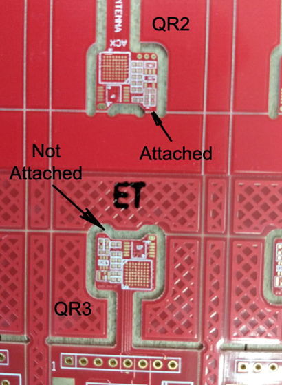
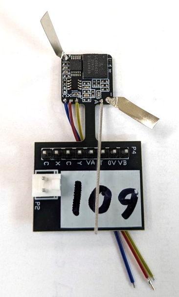
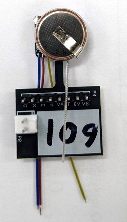
[08-AUG-22] We have a batch of A3028E coming along. It's time for QC2, but the tabs do not lend themselves to the attachement of the CR2330 battery required by the SCT. The figure below illustrates correct and incorrect tabs.
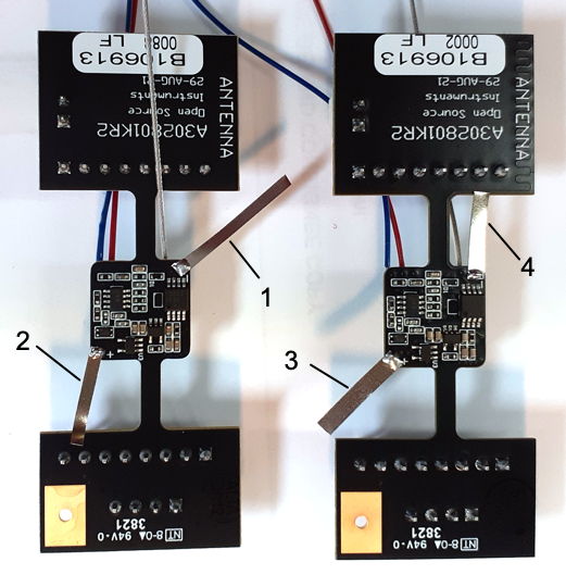
The view above shows us the bottom side of the circuit board, where the tabs are loaded. The tabs wrap around from the bottom of the board to the battery on the top side, and by wrapping around the corner they are less vulnerable to tearing.
[12-OCT-22] We receive A3028S2 number S217.100, manufactured 08-FEB-21 back from ION/UCL. It will not turn on. Dissect and find current consumption is 30 mA through meter with 2.7 V applied, battery is drained completely. Magnet does not have any effect. Dissect, removing C2, U1, U2, C3 and finally U9, at which point current drops to 48 μA. Diagnosis: static damage to VCO.
[27-OCT-22] We are modifying KV2 assemblies to make G3Z. The DC gain of the X and Y amplifiers is ×50 and ×100 respectively. One of our concerns is the input offset voltage of U5 and U6, both OPA2349. As we modify the boards, we program them and connect an external battery VB = 2.8 V. We record the average value of X and Y with inputs open-circuit.
According to the op-amp data sheet, typical range for input offset voltage is ±2 mV. Our op-amps appear to lie in this range. The G3Z input dynamic range for X is nominally −36..+18 mV and for Y is −18..+9 mV. With ±2 mV input offset, we are still sure to see a top-side limit of +16 mV and +7 mV, which is adequate for the EEG (electroencephalogram) and EGG (electrogastrogram) in rats.
[09-NOV-22] We measure the input offset voltage of X and Y channels by shorting the two inputs together and measuring average value.
[14-NOV-22] We remove D1 and D2 from three A3028KV2 with G3Z modification. The offset on channel X changes by −4.7 mV for No43, but ±1 mV for the rest. The leakage current through each diode is of order 1 nA, which developes 10 mV across our 10 MΩ input resistor. We remove D1 and D2 from all fourteen of a batch of G3Z. We add 2 MΩ from U6-6 to VA, see S3028G3Z, in order to bring down the average value of Y provided to the ADC. We do this by soldering a P0402 resistor from one end of the C18 footprint to U6-8. Now we measure offset voltage again.
The removal of the diodes causes no significant change in the X input. The addition of R1 causes a +7.7 mV change in the Y offset, resulting in the average value of Y being 35 kcnt, which is close to half of 67 kcnt.
[04-JAN-23] We program an A3028H2 such that its transmit clock period is 211 ns and measure active current 75.9 μA. We program the same board to clock period 196 ns and active current is 72.3 μA. We have 22 of A3028KV2 programmed as A3028H2, 512 SPS. Maximum current consumption is supposed to be 83 μA. We have three with current 84-86 μA. We reprogram these with 64 SPS and see active current 28, 27, and 28 μA. We take another transmitter, one with active current 74 μA and reprogram for 64 SPS. It's active current is 26 μA. We take No203 with active current 78 μA and No217 with active current 86 μA and reprogram with same sample rate but disable the VCO. Current is 50 μA and 51 μA respectively. The VCO on No217 consumes 35 μA at 512 SPS, while the VCO on No203 consumes 25 μA. We suspect static damage to the VCO during modification, programming, or washing.
[25-JAN-23] We have four A3028B3 that fail QC1 because of excessive current consumption, which we deem to be any active current ≥ 22+(512*0.12) = 83 μA. These are A3028KV2 assemblies. On each, we replace the MAX2623, wash, dry, and measure consumption once again. We see 88 μA drop to 78 μ, 85 μA drop to 77 μA, 83 μA drop to 80 μA, and 86 μA drop to 76 μA. In replacing the MAX2623 we used two brand new parts followed by two reccycled parts.
[26-JAN-23] We have No12 from a batch of A3028B made with A3028KV2 draining its battery. Remove battery and see 100 mA going in at 2.7 V. Remove MAX2623, LC4064ZC, SiT1532, and TPS79718, still draws 100 mA. Sand down cut where programming extension was removed, still 100 mA. Remove SN74AUP1G80DCK and current drops to 0 mA. We hypothesize that spot-welding the tabs, accompanied with touching one of the pins of the power connector on the mounting extension could cause the battery voltage to rise to tens of volts and blow the SN74AUP1G80DCK. We examine the battery tabs and see pairs of welds, so there was no single-sided application of the probes.
[23-FEB-23] We have B214.35 set aside for poaching because it failed QC2 with switching noise. After fifteen days poaching, if fails. Twice we removed rust from outside of antenna. There is a breech in the antenna insulation. Assuming the breech was the source of the current drain that exhausted the battery nine days early, the drain was of order 30 μA, which is consistent with current flowing from VBAT or 0V through 50 kΩ to VC. The resistance of our poaching water appears to be of order 1 MΩ.
[03-MAR-23] We re-work the P3028C03 firmware so as to permit sampling at different rates on the two channels. We use a sixteen-step sample counter as in P3047A01. We remove support for uniform sampling. We cull the old version numbers. We create A3028K1, 0.3-40 Hz, 128 SPS on X, 1-200 Hz, 64 SPS on Y. Current consumption should be 45 μA. We measure 43 μA. Operating life 69 days with CR1620 battery. These are for EEG/EMG, where we measure only the amplitude of the EMG.
[24-APR-23] We apply a 10-mVpp sinusoidal sweep through 100 kΩ to the X-input of an A3028K1, while shorting the Y inputs. We do the same to the Y-input while shorting the X-input. The K1 provides 0.3-40 Hz filtering and 128 SPS on X, a differential amplifier with 1-200 Hz filtering and 64 SPS on Y. Crosstalk between the channels appears to be −40 db (1% in amplitude).
We leave both inputs open-circuit and measure input noise. We see 6 μV rms on each channel, no sign of any 64-Hz harmonic.
[25-APR-23] We have been loading the CR1620 battery on KV2 assemblies. Our preferred tab arrangement is as follows.
[07-MAY-23] We have EEG/EMG recordings from Bristol University made with A3028J3 transmitters. We plot EMG amplitude versus time for two hours.
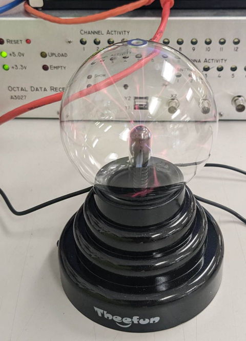
[08-MAY-23] Nathan reports as follows. "Today we conducted an experiment involving using a plasma ball to deliver shocks to an SCT. We began by placing a conductive material (in this case a washer) on top of the plasma ball. Then, we brought the input leads of the SCT close to the washer and allowed for electrons to jump from one conductor to another. This electric shock can cause the transmitter to turn on/off. While static shocks on the inputs can turn the transmitters on/off, the shocks we were applying with the plasma ball weren't enough to damage it. Each time the shock changed the on/off state of the SCT we checked its transmission again and saw it return to normal after saturating. I'm attaching an image of the plasma ball we used with the washer on top of it."
[09-MAY-23] Nathan reproduces the "corrosion saturation" problem, which our collaborators at ION call the "crashed signal" problem. He reports as follows.
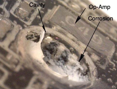
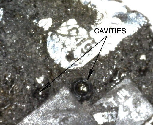
Today we experimented with one of the transmitters Sam and I made (Q3 transmitter number 75). After dissecting the transmitter by unloading the battery, we notice that there is a large cavity in the center of the epoxy (about 2.8mm in diameter). This encourages us to perform an experiment involving the dissected Q3 transmitter by placing a droplet of water in the cavity while measuring the transmitter's frequency response. At first after adding a drop of water, we notice the output of the transmitter is attenuated. After leaving the transmitter running with water in the cavity, the signal began to saturate to the top rail. Leaving it running even longer causes the transmitter's output to alternate between the bottom and top rails before eventually settling on one or the other. We take out the transmitter and notice corrosion inside the cavity. To determine what short causes the bottom saturation effect, we take a new KV2 circuit and short pads together with solder blobs until we see similar symptoms. Shorting R20 causes the transmitter to transmit at the wrong frequency. Shorting C14 or R14 attenuates the output. Shorting pins 2 and 3 of U6 (the topside op-amp) causes the output to saturate to the top rail. Shorting pins 3 and 4 causes the output to saturate to the bottom rail. After imaging the cavity, sure enough we notice a corrosion short between pins 3 and 4 of U6. We then dissect the transmitter sent back by Yunan (225.197) and notice similar cavities in the epoxy on the top side; however, the bottom side channel was the one that saturated at the bottom rail. We couldn't find any cavities on the bottom side, but there were two noticeable cavities on the top side.
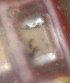
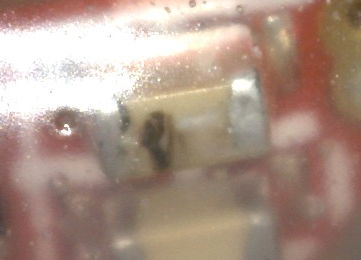
Nathan's conclusion: a cavity around the op-amp pins is a site for condensation and subsequent corrosion, leading to saturation. In the figure below we see white corrosion residue around the pins.
In transmitter H2 No197 returned from ION, we see cavities in the epoxy on the top side. The top side is the one upon which we load the battery, so what air remains in our vacuum chamber during encapsulation will be compressed into bubbles in the top-side epoxy. We don't see such cavities in the bottom-side epoxy.
Nathan tried to destroy an A3028S2 transmitter by connecting its red and blue leads to our battery tab spot-welding machine. After many pulses, the A3028S2 continues to transmit. We leave it running overnight to see what it will do.
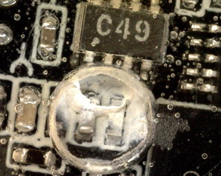
[22-MAY-23] We have an A3028P2 encapsulated in clear DP270 epoxy. After nineteen days poaching at 60°C, we see two rust-brown marks on C4, which is the decoupling capacitor for the logic power supply.
We remove silicone and and epoxy. We confirm marks are indeed on the surface of the capacitor. Nathan reports, "I dissected the P2 transmitter that I made (209.74) and discovered that there was some corrosion developing on the capacitor C4. I took off the battery, measured its current consumption: I_off= 1.5uA; I_on=54.0uA. Then I removed C4 and remeasured its current consumption: I_off=1.2uA; I_on=56.5uA. The transmitter had a life of between 12 and 19 days and suffered a corroded capacitor drain."
[24-MAY-23] We have been poaching an A3028P2 encapsulated in clear epoxys. It runs for twenty days and stops. We see corrosion on capacitor C4 again.
[26-MAY-23] We are retiring the long-running A3028 circuit. Development on corrosion, static damage, encapsulation, and all other matters relating to the design and construction of subcutaneous transmitters is moving to the development pages of the A3047, A3048, and A3049.