| Introduction |
| Springs and Cables |
| Spring Leads |
| Cable Antennas |
| Insulation Removal |
| Solder Joints |
| Silicone and Solvents |
| Development |
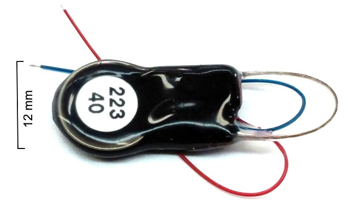
[06-JAN-25] Our implantable, wireless devices demand flexible leads and antennas. Our Subcutaneous Leads (SCL) are silicone-insulated, stainless steel springs. They stretch and they bend. They are fatigue-resistant and corrosion resistant. We use them as electrode leads in Subcutaneous Transmitters (SCT) and as stimulus leads in Implantable Stimulator-Transponders (IST). Our Subcutaneous Antennas (SCA) are silicone-insulated, stranded, stainless steel cables. These implantable, wireless devices are coated in silicone, which joins with the silicone of our SCLs to make an unbroken water barrier around the leads, battery, and electronic circuit of the device. We sell SCLs separately for our customers to use in their own imlantable devices.
Both our leads and antennas must survive months of implantation in freely-moving animals. They will be immersed in saline at 37°C. They will be bent hundreds of thousands of times per day. We present our development of long-lasting implantable leads and antennas in Development of Flexible Wires. We present auxilliary work developing a water-proof encapsulation in Development of Encapsulation. In the passages below, we present details of the wires and cables we use in our leads and antennas. We provide instruction on removing silicone and tinnning in preparation for soldering.
[31-OCT-25] The table below lists the stainless steel springs and stranded cables we use for our leads and antennas respectively.
| Type | Description | Source | Uses |
|---|---|---|---|
| Spring | Pitch 175 μm, OD 450 μm, ID 250 μm, Wire 100 μm 316SS | MDC13867A | B Lead |
| Spring | Pitch 100 μm, OD 250 μm, ID 150 μm, Wire 50 μm 316SS | MDC23172A | C Lead |
| Spring | Pitch 300 μm, OD 500 μm, ID 200 μm, Wire 150-μm 316SS | MDC26398 | D Lead |
| Stranded | Strands 7×7, OD 360-μm, Wire 302SS | Sava 2014 | A/B Antenna |
| Stranded | Strands 7×7, OD 250-μm, Wire 302SS | Sava 2010 | D/E Antenna |
The figure below shows the three types of spring next to one another.
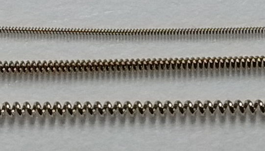
All these springs were made by the micro-spring manufacturer Motion Dynamics Corporation.
[31-OCT-25] Our spring leads are 316SS helical wires insulated with silicone. They stretch along their length and bend easily. They survive the repetitive stress of implantation indefinitely, so long as they are not bent sharply at the point where they emerge from the dental cement of a head fixture. We have three sizes of spring for lead manufacture: 50-μm wire in a 250-μm outer diameter, 100-μm wire in a 450-μm outer diameter, and 150-μm in a 500-&muy;m outer diameter. We use these to make our C, B, and D-Leads respectively.
All our spring leads are coated with unrestricted, medical-grade silicone, MED-6607. The inner silicone is SS-5001 with a dye added to give the lead a bright color. The dyes we keep in stock are: blue, red, orange, purple, yellow, green, pink, or brown. Once insulated, our three sizes of spring attain an insulated outer diameter of 0.5-mm for the C-Lead, 0.7-mm for the B-Lead, and 0.8-mm for the D-Lead. The figure below is a mechanical drawing that provides both dimensions and tolerances of the insulated leads. For a table of tolerances, resistance, and maximum lengths, see the Leads chapter of our Telemetry Manual

When we are recording EEG or EMG, we are not concerned about lead resistance, because the input resistance of our amplifiers is of order 10 MΩ, which is very much greater than the lead resistance. When we want to tens of milliamps through a 130-mm lead for stimulation, however, we recommend our 0.7-mm leads, which present a lower resistance.
Our 0.5-mm leads are eight times more flexible than our 0.7-mm leads, but the breaking strain of their steel wire is four times lower. In rat and mouse pups, the greater flexibility of the 0.5-mm leads justifies their greater fragility. But in larger animals, we recommend the more rugged 0.7-mm lead. When we remove silicone from the tip of a 0.5-mm lead, we must cut the silicone around the circumference of the lead with a scalpel and unscrew the silicone from the tip of the lead. See the Insulation Removal chapter of this page for detailed instruction and videos of the removal procedure.
We sell insulated leads separately if you need them for your own purposes, under the family part number "SCT". The part number for a given lead is SCL-diameter-length. Thus SCL-0.7-130-Blue is a 0.7-mm diameter lead 130 mm long and dyed blue, SCL-0.5-130-Red is a 0.5-mm diameter lead 100 mm long, dyed red. See our Price List the price of our leads. Available lengths are 130 mm and 280 mm. Colors are blue, red, orange, purple, yellow, green, pink, or brown.
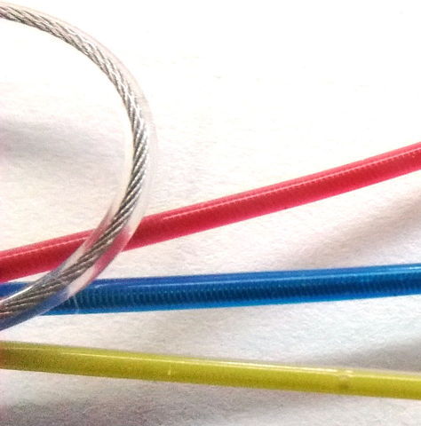
[27-JUN-25] We use strain-relieved, bare, 7×7 stranded, stainless steel cable for implantable antennas. We insulate them in clear, unrestricted, medical-grade silicone. In our A and B-Antennas we use 350-μm diameter cable. In our D and E-Antennas, we use 250 μm diameter cable. The A and B-Antennas are the thickest and toughest antennas. The D and E-Antennas are the most flexible. They are for implantation in mice, where we do not expect the implantation to last more than a few months.

Stranded wire offers the best compromise between transmission efficiency and fatigue resistance. Stranded wires cannot endure repetetive stretching for months, but they can endure repetetive flexing, which is all that is required of an antenna. We prefer to use stress-relieved cable because it is easier to work with, but our thinner antennas are not strain-relieved, so the wires spread when we cut them, and we must use various tricks with knots to insulate and tin them.
For a table presenting the characteristics of our A, B, D, and E antennas, see the Antennas chapter of the Telemetry Manual. We discontinued the "C-Antenna", which was an antenna made out of a spring lead rather than a stranded cable. The C-Antenna was inefficient.
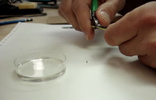
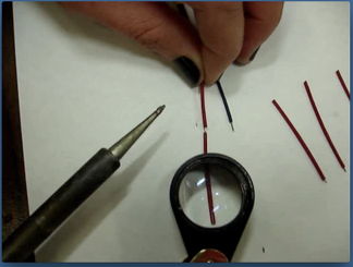
[04-APR-21] Silicone adheres well to our spring wires. It cannot be burned off. It cannot be scraped off. we want only a millimeter of straightened wire, we can grab the tip of the wire at the end of the lead and pull. Now we can bend and cut to length in preparation for securing with a screw or cyanoacrylate. But if we want to solder the wire to a screw, or attach it to a crimp ferrule, we need to expose at least a millimeter of the spring wire. To remove the insulation, we use a scalpel and a flat surface. The tutorial movie below shows how to remove silicone from one of our 0.7-mm diameter leads.

The procedure for our 0.5-mm diameter leads is similar, but more delicate. We have an additional movie to explain the extra precautions one must take to remove the silicone from these smaller leads.

[06-JAN-25] The video below shows how to tin a stainless steel spring with acid flux, and solder it to a pin. In the video we claim that you can use hydrochloric acid as flux for soldering stainless steel, but we recommend you use zinc chloride acid flux. Later comparisons between hydrochloric acid and zinc chloride flux showed that the former was greatly inferior to the latter.
Our soldering iron is temperature-controlled. Acid flux gives the best performance with the iron at 400°C. Once the wire tip has been tinned with the help of acid flux, it can be soldered at any time. The flux we use in the video is the No75 zinc chloride acid flux from Superior Flux Company, which we purchase from McMaster. We have also made our own zinc chloride flux using the following recipe, but we recommend against embarking upon this procedure if you can avoid doing so: you need an extraction hood or an outdoor work space.
The following video shows how one can extend spring leads that have been cut short, perhaps after removal from an animal. Lead extension is of particular importance in work with mice, where we begin with 45 mm leads and require at least 40 mm to make the journey from the implant to the brain. If we start with more than 45 mm, the leads bend and overcrowd the mouse.
Instead of extending your leads, we recommend you order long leads to begin with, allowing for 5 mm to be cut off every time you explant the device. Lead extension is something we can do for you if you accidentally order implants with leads that are too short. You can send them back to us and we will extend the leads for small fee.
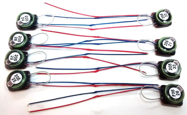
The particular batch shown above we shipped with 45-mm long leads, when the customer really wanted 90-mm leads. Each lead is now extended to 90 mm. The solder joint at the center is covered by three layers of silicone.
WARNING: We encourage you to wash and sterilize your implantable devices by shaking them for up to ten minutes in acetone, ethanol, acetic acid, or soapy water. But do not store your implantable devices in any fluid. Before storage, wash with water and allow to dry. Store in a dry place. In particular: do not soak implantable devices in ethanol for more than ten minutes.
[12-FEB-26] We encapsulate our implantable devices in black epoxy and then coat them with silicone. Our antennas we make out of 304SS or 316SS steel cable coated with silicone. Our electrode leads we make out of 316SS springs coated with silicone. The outer coating of silicone on leads, antennas, and implant bodies is always unrestricted, medical-grade MED-6607.
Silicone and epoxy do not react with water or saline, but they are both permeable to water vaport. Wash your implants in hot water but do not store them in water. Store them in a dry place so as to ensure that no corrosion of the implant circuit takes place before implantation.
Our customers often use cyanoacrylate adhesives to fasten electrodes in place. Cyanoacrylate dissolves slowly in acetic acid. We placed two fully-encapsulated A3028B transmitters in acetic acid at 60°C for a week. They still functioned perfectly afterwards. We saw now change in the silicone coating. It appears that silicone resists acetic acid very well. We have heard no reports of animals reacting badly to silicone that has been soaked in acetic acid. Feel free to soak your implants in acetic acid, but do not store them acetic acid. Store them in a dry place.
Stirring or shaking in ethanol for ten minutes at room temperature is a good way to disinfect an implantable device, but we ask you not leave your implants in ethanol for more than ten minutes. We are certain that at least three implants that failed prematurely in the field after being stored in ethanol, and we are confident of half a dozen other failures in the field for the same reason. In one of our experiments, soaking four implants in ethanol for one hour at room temperature caused no damage, but soaking for four hours damaged all four. Soaking in hot ethanol for three days causes visible stress to an implant's silicone encapsulation. We stored five implants in ethanol at room temperature for a month, after which one of them would turn on, and it transmitted only zeros. When we squeezed these devices, ethanol squirted out through a hole in the silicone. Upon dissection, we found the surface of the silicone to be slimey, and the adhesive beneath the device's serial number sticker had become a sticky mess. Ethanol slowly dissolves in epoxy, so the inner epoxy encapsulation of our implantable devices will eventually be compromised exposure to ethanol even at room temperature. To be certain that ethanol does not damage your implantable devices, do not leave them in ethanol for more than ten minutes.
Most of our customers use cold-cure dental cement to construct head fixtures to hold screws, pins, optical fibers, and guide cannulas in place on the skulls of their laboratory animals. Dental cement dissolves over-night at room temperature in acetone, so we would like to use acetone to remove dental cement from explanted implants and their leads. Acetone at 60°C damages our silicone coatings within twenty-four hours. At 60°C, silicone swells up as it dissolves one quarter of its mass of acetone. Room temperature acetone acts far more slowy. We recommend soaking in 20°C acetone for six hours in order to dissolve dental cement. Place the implant with head fixture in a jar of acetone. After six hours, shake vigorously. Wash the implant in fresh, clean acetone twice, so as to remove all traces of dissolved cement. Leave the implant in air for a day to allow any acetone dissolved in the silicone to evaporate. For further details of our tests with silicone and acetone see the Flexible Wire Development Page. Before storage, wash with water, dry, and store in a dry place.
[06-JAN-25] For a chronicle of our work on flexible leads for implantation, including our studies of fatigue and corrosion, see Development of Flexible Wires.