Battery Charger (A3033)
© 2017-2024 Kevan Hashemi,
Open Source Instruments Inc.
Contents
Notice of Obsolescence
Warnings
Description
Versions
Design
Batteries
Diodes
A3033A
A3033B
A3033C
A3033D
A3033E
A3033F
Development
Notice of Obsolescence
[27-JUL-22] The Battery Charger (A3033) is obsolete. We no longer manufacture any rechargeable implantable devices. Any future non-implantable instruments we make that require recharging will be rechargeable with a USB power plug, so we will have no need for the A3033. Recharging implant batteries proved to be a point of failure in the telemetry and stimulator systems. We could connect a device to the charger and believe we had charged it up after a few days, when all along the charging leads were the wrong way around. Or we might use the wrong charger with a device and it would fail to charge, or suffer damage. Furthermore, the lithium-polymer batteries we were fond of using would swell up if left uncharged, emitting a sweet-smelling gas and cracking their epoxy encapsulation.
Warnings
Warning: Using the wrong charger with your implant can damage its battery. The charger version letter is written on the modular plug boot.
Warning: The chargers will not operate when plugged into an ethernet switch.
Warning: Don't place the charger on a metal surface. If the charging clips are connected with metal, your device will not charge.
Description
[08-DEC-19] The Battery Charger (A3033) is a LWDAQ device that perform ex-vivo recharging of implantable devices equipped with lithium-polymer (LiPo) or manganese-lithium (MnLi) batteries. All versions of the A3033 use a LWDAQ driver socket as a source of power, and require no adjustment or monitoring other than, in some cases, limiting the maximum time the battery is connected to the charger. We connect the leads of an implantable device to the correct clips provided by the charger and the battery begins to recharge.

Figure: Implantable Stimulator-Sensor Charger (A3033C). Assembly number A3033C writton on back side of board. Red circle with X for red X+ lead. Adjacent blue circule for blue X− lead. Orange circle with L for orange L+ lead. Adjacent purple circle for purple L− lead.
All versions of the A3033 consist of a cable that plugs into a LWDAQ Driver, a body that contains the recharging circuit, and two or four smooth-jawed clips to hold the charging electrodes of an implantable device. These clips may be on their own color-coded leads, or they may be soldered onto the charger circuit baord. The chargers produce different voltages and impose different current limits, so that some chargers will damage some implants, and other chargers will fail to charge other implants. Check the version letter of your charger against the version of your implant.
Versions
The following versions of the Battery Charger (A3033) exist.
Table: Versions of the Battery Charger (A3033). The minimum charge time is the time required to get to 90% of full charge. The maximum charge time is the time beyond which the battery may be damaged by over-charging.
The cable is terminated with a modular connector plugs. We plug this into any unused socket of a LWDAQ Driver. The LWDAQ Driver supplies power to the charger. The charger's regulator is potted in epoxy within the black-wrapped section of the charger. Two or four flexible leads with stainless-steel, smooth-jawed clips allow us to connect to miniature pins, bare wires, or screws. The clips deliver a charging voltage with current limiting to the implantable device through its charging leads. The positive charging lead is red or orange. The negative charging lead is black, blue, or purple.
Design
S3033A_1: Schematic for original single-cell charger.
S3033B_1: Schematic for dual-cell charger.
2N3904: Bipolar transistor used as voltage source.
DMP2004VK: Dual mosfet with clamping diode used in IST (A3036) charging circuit.
RYM002N05: Single mosfet with clamping diode used in ISS (A3037) stimulator charging circuit.
BAS116LPH4: Low-leakage diode used in SCT (A3028) charging circuit.
A303301A.zip: Gerber files for A3033C printed circuit baord.
A303301A_Top: Top view of A303301A printed circuit board.
A303301A_Bottom: Bottom view of A303301A printed circuit board.
Batteries
Almost all the Subcutaneous Transmitters (SCT) we sell are equipped with non-rechargeable lithium primary (Li) cells, either from the BR Series or the CR Series. These batteries produce a voltage of around 2.6 V for most of their operating life, and their charge capacity per unit volume is at least double that of any other battery family. When we equip SCTs with these batteries, their operating life for continuous experiments is at least double that of a device of the same volume equipped with any other type of battery.
Figure: Example Discharge Curves for Lithium Primary Batteries. We discharge five CR1025, 30-mAhr, 3-V cells with five A3028P3 transmitters, channel numbers given in legend, each consuming ≈75 μA, expected life is 400 hr, observed life is 391-410 hr. We measure VBAT by taking the average of one second's worth of X samples. The average value of X corresponds to VCOM, which is 1.8 V. From this we deduce VBAT, which corresponds to a X = 65535.
There are two applications where we have found rechargeable batteries offer a solution where non-rechargeable batteries do not. One is when we want the smallest possible battery, for the smallest possible battery that can provide the minimum 2.3 V needed to drive an SCT is a rechargeable battery. The other is for optogenetic stimulators, for the batteries that have the highest capacity to deliver current for light-emitting diodes are rechargeable batteries.
Our rechargeable manganese-lithium (MnLi) batteries are circular disks. Their charge capacity is measured in milliamp-hours (mA-hr), so that the product of current and time is a constant, within limits. Their output voltage is close to 2.5 V during their entire discharge. The ML920 is 9.5 mm in diameter and 2.05 mm thick, with capacity 11 mA-hr and source resistance 60 Ω. The ML621 is 6.8 mm in diameter and 2.15 mm thick, with capacity 5.0 mA-hr and source resistance 80 Ω. These batteries are not suitable for implantable stimulators that drive light-emitting diodes (LEDs). When delivering 10 mA, the ML920's output voltage will drop from 2.5 V to 1.9 V, which is barely enough to illuminate a red LED, let alone a green LED. But MnLi batteries are easy to charge, because we can charge them slowly and have no fear of damaging them. We connect a charging voltage through a resistor to the charging leads of the implantable device, and let it sit for forty-eight hours. After twelve hours the battery will most likely be fully-charged, but additional charge current does no damage.

Figure: Example Discharge Curves for Manganese-Lithium Batteries. We charge the batteries through a 400-Ω resistor using various voltages 2.9-3.3 V. The ML621 is 6.8 mm dia, 2.1 mm thick, 5.0 mA-hr. The ML920 is 9.5 mm dia, 2.0 mm thick, 11 mA-hr.
Our rechargeable lithium-polymer (LiPo) batteries come from various sources. They are all rectangular, so they have length, width, and depth measured in millimeters. When we buy a new batch of them, we can usually get something almost identical to what we purchased before, but rarely will it be exactly the same part number from the same manufacturer. Their capacity is also measured in mA-hr. Their voltage, when freshly charged, will be around 4.2 V, but quickly drops to 3.8 V, declines slowly to 3.5 V, and then collapses rapidly to zero if current drain continues.

Figure: Example Discharge Curves for Lithium-Polymer Batteries. Each chart is C/I where C is nominal battery capacity in mA-hr and I is current drain through a transmitter in μA. The fraction thus expressed is the expected operating life in thousands of hours. We charge with a 4.2-V source current-limited to 20 mA for 19-mAhr and 150 mA for 190 mA-hr batteries.
We use LiPo batteries in our implantable stimulators because they are the only miniature batteries capable of delivering tens of milliamps to an LED. Their output resistance is an order of magnitude lower than that of MnLi or Li cells. Our 19 mA-hr LiPo battery has output resistance 5 Ω, while our 190 mA-hr LiPo battery has output resistance 1 Ω. These batteries can deliver 30 mA to an LED easily. Their higher output voltage means they store more energy, which is not useful when powering an SCT that requires only 2.3 V, but is useful when driving a blue LED that requires 3.0 V.
But LiPo batteries are more difficult to use. If we allow them to discharge completely, they lose half their capacity, as we describe in Discharge Rate and Capacity. So we must be sure to monitor their voltage during use, and turn them off before their output voltage drops below 3.4 V. When we charge them up, we must limit the charging current and the charging voltage or else they will over-heat and lose some portion of their capacity, or start to swell and crack the epox encapsulation of the implant.
The ideal way to rechrage a LiPo battery is to connect it to a bench-top power supply set to 4.2 V output with current limit set to the C, where C is the numerical value of its capacity in mA-hr. So a 19 mA-hr battery we charge with a 19 mA-hr current limit. At first, the power supply will apply something like 3.5 V to the battery and 19 mA will flow in. After half an hour, the battery will have charged to 3.7 V and 10 mA will be flowing in. After two hours, the current will be 1 mA or so, and the voltage will be 4.2 V. Now we disconnect the charger.
Neither terminal of the battery of an implantable devices is accessible to us directly. We must charge the battery through a pair of leads, each of which present a resistance of 10-100 Ω, depending upon the device. Once the charging current reaches the base of the leads, it must pass through one or two diodes before reaching the battery. In SCTs, we use the sensor leads, and the current must pass through two diodes. In ISTs, we use the stimulator leads, and the current must pass through one diode. The diodes are what makes it possible to use the leads for charging as well as their sensors or stimulators. The diodes and lead resistance make recharging the battery more difficult.
Diodes
The rechargeable versions of our Subcutaneous Transmitter (SCT, A3028) are made with the A3028PV1 circuit board, circuit schematic S3028P. This circuit provides only one amplifier, so all rechargeable versions of the A3028 are currently single-channel devices. Their input leads are X, a red or yellow lead, and C, a blue lead. Recharging takes place through diodes D1 and D2, which are BAS116LPH4. The plot below gives the forward current versus forward voltage relation for these diodes at various temperatures. Our chargers assume that the ambient temperature will be close to 25°C.
Figure: Current versus Voltage for the BAS116LPH4 Diode. Charging current passes through two such diodes on its way to the battery in all rechargeable versions of the Subcutaneous Transmitter (A3028) and the master battery of the Implantable Stimulator-Sensor (A3037).
The Implantable Stimulator-Transponder (IST, A3036) input leads are L+, a red or orange lead, and L−, a blue or purple lead. From the base of the L+ lead, charging current passes directly into the battery's positive terminal. This same current emerges from the battery's negative terminal and passes through one diode before reaching the base of the L− lead. The plot below gives the characteristics of this diode as measured in an IST circuit.

Figure: Current versus Voltage for DMP2004VK Body Diode. Charging current passes through one such diode on its way to the battery of the Implantable Stimulator-Transponder (A3036).
At 0.45-V forward voltage, the current is 30 μA through the diode, which will take many days to damage a fully-charged battery. If we want to charge to 4.25 V, a charging voltage of 4.70 V with a series resistance of order 100 Ω will provide safe charging over about eight hours to a 19 mA-hr battery. The Implantable Stimulator-Sensor (ISS, A3037) is loaded with two batteries, one for the master and one for the slave. The master battery we charge through two BAS116LPH4, as described above. The stimulator battery we charge through the clamping diode of an RYM002N05 mosfet, whose characteristics we plot below from our own measurements.
Figure: Current versus Voltage for RYM002N05 Body Diode. Charging current passes through one such diode on its way to the stimulator battery of the Implantable Stimulator-Sensor (A3037).
If we apply 4.4 V with current limit 10 mA through one of these diodes to a 10-mAhr LiPo battery, the battery will charge to 4.15 V and 100 μA will continue to flow in through the mosfet diode.
A3033A
The A3033A is a charger for small lithium polymber (LiPo) batteries with one silicone diode in series. It provides a 4.7-V charging voltage with source resistance 60 Ω. The source resistance combined with the resistance of the leads provided by the rechargeable device serve to limit the current flowing into the device's LiPo battery.

Figure: Implantable Stimulator-Transponder Charger (A3033A). Compatible with A3036 with ≥10 mAhr LiPoA. Letter A written on connector boot.
The A3033A is compatible with the IST A3036 with ≥10 mAhr LiPo, which it will charge in 8 hr. The A3033A's quiescent power consumption is 300 mW, confined within its epoxy-encapsulated body. Over the first ten minutes, the circuit heats up, and this results in its output voltage rising by roughly 0.07 V. After that, the output voltage is stable. We adjust the A3033A's output voltage so that it will be 4.7±0.05 V when warmed up. The output current of the A3033A is limited by its own output resistance, so it is not possible to damage a LiPo battery with the charger, nor to damage the charger with a short circuit.
Figure: Output Voltage versus Output Current for A3033A Charger.
The plot above shows the decline in output voltage with increasing current for four A3033A chargers. The initial slope is ≈ −60 Ω. The final slope is ≈ −200 Ω.
A3033B
The A3033B is a charger for small manganese-lithium (MnLi) batteries with two silicon diodes in series. It provides a 4.2-V charging voltage with 1-kΩ source resistance. The source resistance limits the current that flows into the battery to one or two milliamps.

Figure: Tiny Subcutaneous Transmitter Charger (A3033A). Compatible with A3028TR. Letter B written on connector boot.
The A3033B is designed to charge MnLi batteries through the EEG leads of a rechargeable SCT. The A3033B is compatible with the SCT A3028TR, which it charges in 48 hr.
A3033C
The A3033C is a dual-battery charger for the master and stimulator batteries of an Implantable Stimulator-Sensors (ISS) such as the A3037A. The charge currents are limited to 10 mA for use with LiPo batteries with capacity ≥10 mAhr. The CH1+ and CH1− clips charge the master battery through the red X+ and blue X− leads respectively, while the CH2+ and CH2− clips charge the stimulator battery through the orange L+ and purple L− leads respectively.
Figure: Implantable Stimulator-Sensor Charger (A3033C). Assembly number A3033C writton on back side of board. Red circle with X for red X+ lead. Adjacent blue circule for blue X− lead. Orange circle with L for orange L+ lead. Adjacent purple circle for purple L− lead.
The A3033C will charge both batteries in 2 hrs. Both chargers are designed to deliver 100 μA to their batteries when the battery voltage has reached 4.2 V.
Figure: Output Voltage versus Output Current for A3033C and A3033D Chargers. X: The A3033C CH1 charging voltage. L: The A3033C CH2 charging voltage. S: The A3033D CH1 and CH2 charging voltrages.
The design assumes that the master battery charge current passes through two BAS116LPH4 diodes, which each drop 0.64 at 100 μA and 25°C. Hence CH1's voltage limit is 5.48 V. The stimulator battery current passes through one RYM002N05 body diode, which drops 0.26 V at 100 μA, so CH2's voltage limit is 4.46 V.
A3033D
The A3033D provides two chargers for devices with a single DMP2004VK body diode in series with a lithium-polymer (LiPo) battery with capacity ≥10 mAhr, such as the Implantable Stimulator-Transponders (A3036A) with ≥10 mAhr LiPo. The CH1+ and CH1− clips charge one device through its orange L+ and purple L− leads respectively, and the CH2+ and CH2− clips charge another device in the same way. Maximum charging current is set to 19 mA, so the charge time for a 10-mAhr battery is less than one hour. Leave devices connected for no more than 48 hrs to avoid over-charging the batteries.

Figure: Implantable Stimulator-Transponder Charger (A3033D). Assembly number A3033D writton on back side of board. Orange circle with S for orange L+ lead. Adjacent purple circle for purple L− lead.
Both chargers are designed to deliver 100 μA to their batteries when the battery voltage has reached 4.2 V. For the charging voltage versus current behavior of the A3033C's CH1 and CH2 chargers, see above. The design assumes that the batttery charge current passes through a single DMP2004VK, which drops 0.42 V at 100 μA. Hence the voltage limit is 4.62 V.
A3033E
The A3033E is a dual charger for devices with two BAS116LPH4 diodes in series with a small manganese-lithium (MnLi) battery, such as the Subcutaneous Transmitter (SCT, A3038TR). The CH1+ and CH1− clips charge one battery through its red X+ lead and blue X− leads respectively, and the CH2+ and CH2− clips charge a second device in the same way. Maximum charging current is 5 mA, charging voltage is 4.2 V. A 1 kΩ resistor limits current as the battery charges up, allowing us to leave the batteries charging indefinitely.

Figure: Tiny Subcutaneous Transmitter Charger (A3033E). Assembly number A3033E writton on back side of board. Red circle for red X+ lead. Blue circle for blue X− lead.
A3033F
The A3033F is a dual charger for devices with two BAS116LPH4 diodes in series with a lithium-polymer (LiPo) battery of capacity ≥10 mAhr. Its charging current is 10 mA and its open-circuit output voltage is 5.48 V. Accounting for the voltage drops in the diodes, the charger aims to charge the battery to 4.2 V. Leave devices connected for no more than 48 hrs to avoid over-charging. The CH+ and CH− clips connect to the red C+ and blue C− leads respectively of an Implantable Inertial Sensor (A3035A).
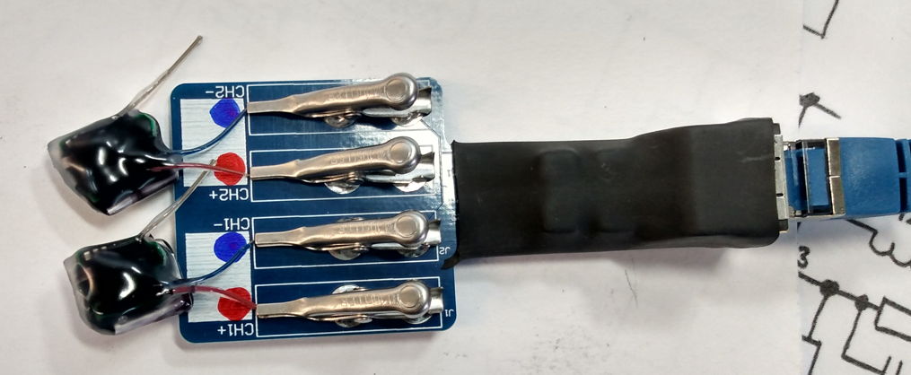
Figure: Implantable Inertial Sensor Charger (A3033F). Assembly number A3033F writton on back side of board. Red circle for red C+ lead. Blue circle for blue C− lead.
Development
[10-DEC-19] We construct our first A3033A, using a commercial ethernet jumber cable with a sliding boot. We adjust the output voltage to 4.70 V and pot in black epoxy.
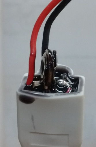
Figure: Construction of the A3033A, Potting the Circuit in Epoxy. The protruding component is the 470-Ω potentiometer we use to set the charging voltage.
[11-DEC-19] We plug our A3033A prototype into a LWDAQ Driver and measure open-circuit output voltage 4.65 V. We load with 1 kΩ and wait ten minutes. The open-circuit output voltage rises to 4.69 V and when loade with 1 kΩ it is 4.38 V. We expect the output voltage to increase as Q1, 2N3904. warms up. From these observations, we deduce output resistance 71 Ω. Short-circuit current is 31 mA, in which state Q1 is saturated and we have 0.5 W being dissipated in R2 = 470 Ω, a 0.25-W resistor encapsulated in epoxy. We connect to an A3036 with 10 mAhr LiPo and see output voltage 4.61 V, which implies 1.1 mA flowing into the device.
[12-DEC-19] The A3028TR, with displacement volume 0.5 ml, is the smallest SCT we make. It turns out that the smallest batteries we can buy are manganese-lithium (MnLi) rechargeable batteries, so the A3028T is equipped with an ML621 MnLi battery with capacity 5.0 mA-hr. To charge the battery, we use a 1-kΩ resistor and two BAS116LPH4 to deliver a 4.2-V charging voltage to the battery. The battery will be fully charged after forty-eight hours. The battery voltage will be 3.0 V and charging current will be 40 μA. Use Battery Charger (A3033B) to get a full charge in 48 hr. Connect the charger's red lead to the red stimulator lead, and the charger's black lead to the blue stimulator lead.
The A3028BR, displacement volume 1.4 ml, is equipped with a 19 mA-hr lithium-polymer (LiPo) battery. We use a 100-Ω resistor and a 5-V charging voltage. We monitor the battery voltage by disconnecting it from its charger every half-hour, turn on the transmitter, and use the average value of its X input to deduce the battery voltage (Vbattery = 65535 × 1.8 V ÷ Xaverage). When the battery voltage reaches 4.2 V, we stop charging. If we continue charging, we will damage the battery.
The A3028ER, displacement volume 4.0 ml, is equipped with a 190 mA-hr lithium-polymer (LiPo) battery. We use a 100-Ω resistor and a 5-V charging voltage. We monitor the battery voltage by disconnecting it from its charger every half-hour, turn on the transmitter, and use the average value of its X input to deduce the battery voltage (Vbattery = 65535 × 1.8 V ÷ Xaverage). When the battery voltage reaches 4.2 V, we stop charging. If we continue charging, we will damage the battery.
The Implantable Stimulator-Transponder (IST) A3036 with ≥10 mAhr LiPo, with displacement volume 0.9 ml, are our smallest rechargeable implantable stimulators. They are equipped with a 19 mA-hr LiPo battery. To charge the battery, we use 4.7-V with source impedance 60 Ω connected to the red (positive) and blue (negative) leads. The charging current flowing into an exhausted battery will no more than 10 mA. The battery will be fully charged to 4.3 V in eight hours. At this point, the current flowing into the battery will be of order 10 μA and we can leave the charger connected indefinitely. Our Battery Charger (A3033A) is designed for use with the A3036A, and provides a full charge in 8 hr. Connect the charger's red lead to the red stimulator lead, and the charger's black lead to the blue stimulator lead.
The Implantable Stimulator-Sensor (ISS) A3037A has two small LiPo batteries that we charge simultaneously with A3033C through the sensor and stimulator leads. Both batteries will be at full charge in 8 hr. Connect the A3033C leads to the leads of the same color on the ISS red and blule leads to the red and blue leads respectively, and connect the A3033C red stimulator lead, and the charger's black lead to the blue stimulator lead.
[28-JUL-20] We receive A303301A printed circuit boards for the A3033C. We assemble and find that the circuit works well after increasing VR2 and VR4 with 10 kΩ. We select 4.45 V and 10 mA to charge VBS on the A3037A, and 5.46 V and 10 mA to charge VBM. In both cases, we are assuming 100 μA through the charging diodes, using the charts above and setting the battery voltage to 4.2 V. The stimulator circuit diode drops 0.25 V at 100 μA, while the two master circuit diodes drop 1.26 V at 100 μA.
[07-AUG-20] We connect our A3033C CH1 to an X and C of an A3037A whose VBM is discharged to 3.5 V. We see 8.1 mA flowing in, VBM = 3.60 V, voltage across charging diodes is 0.72 V each. Time is 14:45. We adjust the current to 11 mA and VBM = 3.80 V. We short VBM to 0VM for three seconds, after which VBM = 3.5 V. We short the output of our current meter and current increases to 12 mA. At 15:30 current is 5.8 mA, VBM = 4.0 V. We connect the CH2 to L+ and L−. We see 10 mA flowing in, VBS = 3.92 V, voltage across mosfet diode is 0.44 V. At 15:50, VBS = 4.00 V, current is 10 mA, and diode voltage 0.44 V.
[10-OCT-20] We have four new A3033D chargers. Of the eight A3036 charging outputs, open circuit voltage is 4.62±0.2 V and short circuit current is 17±0.5 mA.
[19-APR-21] An A3033D at Edinburgh brings down the ±15 V power supplies of the LWDAQ Driver when we connect it to a LWDAQ cable. We leave an A3033D with all its contacts shorted together. After two hours it is slightly warm. We leave it shorted.
[14-MAY-21] We have the faulty battery charger back from Edinburgh. Jordan reports, "After inspecting the battery charger. I determined that capacitor C3 1uF that was between 0V and 15V was blown. It appeared to blow to a short circuit, regretfully I threw it out before inspecting it further. When replaced, the charger behaved as expected and I was able to set the output voltage and current as desired for the D version of the circuit. It seems unlikely that transmitters were exposed to a voltage higher than the rated 4.6 volts. I measured the output voltage while adjusting the variable resistor and saw that the maximum voltage was 3.5V. This output was switching between 3.5V and 0V as the driver power supply switched on and off. However, upon receiving the device the voltage appeared to be around 1.3V on each output. I would expect that failures in the transmitters would be due to lack of charge over an extended period of time."